Understanding Photoelectric Sensor Calibration Fundamentals
Calibration of photoelectric sensors is a critical maintenance procedure that ensures measurement accuracy, repeatability, and system reliability. At its core, calibration involves comparing the sensor's output signal against a known standard or reference under controlled conditions and adjusting its parameters to correct any deviation. This process verifies that the sensor correctly interprets the presence, absence, or distance of a target object. Unlike simple functional checks, true calibration quantifies performance and aligns it with specified tolerances. Factors necessitating calibration include component aging, environmental changes like temperature fluctuations, accumulation of contaminants on lenses, and mechanical vibrations that may misalign the optical path. A well-defined calibration schedule, based on the sensor's criticality and operating environment, forms the foundation of predictive maintenance and prevents costly false triggers or missed detections in automated systems.
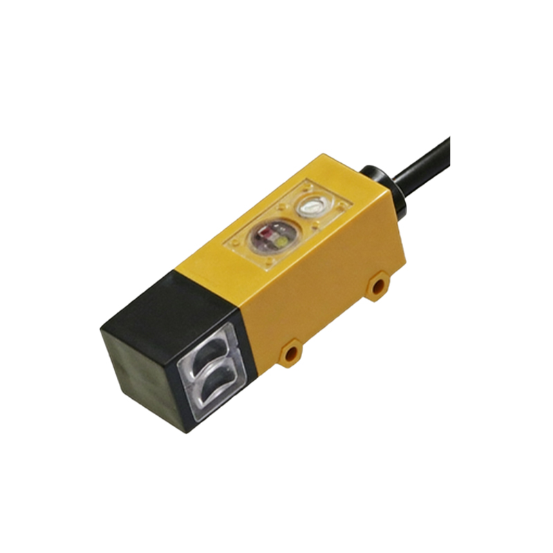
Essential Tools and Equipment for Precise Calibration
Successful calibration requires specific tools to achieve industrial-grade precision. The primary tool is a calibrated reference target, which has known, stable reflectance properties (often 90% white and 18% gray as per DIN standards) and precise geometric dimensions. For distance-sensing or background suppression sensors, a precision positioning stage or gauge blocks are indispensable for setting exact measurement points. A high-quality digital multimeter or an oscilloscope is necessary to accurately read the sensor's analog output current (e.g., 4-20mA) or voltage signal. For sensors with programmable parameters, the manufacturer's dedicated teach-in tool or software interface is mandatory. Additionally, a clean, stable environment with controlled ambient light is crucial, as stray light can severely impact calibration results for diffuse and retro-reflective sensors. Never attempt calibration with makeshift objects, as inconsistent surface properties will introduce significant error.
Step-by-Step Calibration Procedure for Common Sensor Types
The calibration methodology varies significantly by sensor operating principle. For a standard through-beam sensor, the procedure focuses on alignment. After securing the emitter and receiver units on a stable fixture, use alignment lasers (if equipped) or visually align them until the received light signal is maximized, as indicated on the receiver's signal strength indicator. For diffuse reflective sensors, position the standard reference target at the exact specified sensing distance. Trigger the 'teach' function to set the switching point, allowing the sensor to memorize the signal level from the reference. For background suppression sensors, a two-point calibration is often required: first, teach the sensor with the target at the near limit, then at the far limit, enabling it to define its suppression curve. For analog output sensors, apply the minimum and maximum distance/reflectance inputs and adjust the output span and offset to match the specified 0/4mA and 20mA or 0/10V points.
Verification, Documentation, and Post-Calibration Protocols
Calibration is incomplete without rigorous verification and documentation. After adjustment, test the sensor with the reference target at multiple points within its range, not just at the taught points. Check for hysteresis by approaching the target from both directions. Verify the sensor's response to potential false triggers, such as a highly reflective object in the background for a diffuse sensor. All calibration data—initial readings, adjustments made, final verification results, environmental conditions, and the tool identifiers—must be recorded in a calibration certificate or maintenance log. This traceability is vital for quality audits and troubleshooting future drift. Finally, label the sensor with the calibration date and next due date. Implement a system to protect the calibrated sensor from unauthorized adjustment in the field, often through password-protected software or physical seals.
Troubleshooting Common Calibration Challenges and Errors
Engineers frequently encounter challenges during photoelectric sensor calibration. A persistent "signal unstable" error often points to electrical noise, inadequate power supply, or mechanical vibration affecting the fixture. Employ shielded cables, proper grounding, and stable power sources to mitigate this. If a sensor cannot achieve its rated sensing distance even after cleaning, the LED or laser diode may be degrading, requiring replacement. Inconsistent readings may stem from an unsuitable reference target; ensure it is matte and non-metallic if calibrating a standard diffuse sensor. For color contrast sensors failing to distinguish shades, verify that the ambient light conditions during calibration match the operational environment. Always consult the sensor's datasheet for model-specific calibration nuances, as procedures for fiber-optic amplifiers or specialized models like luminescence sensors differ substantially from standard units.