Introduction to Proximity Sensors and Transistor Outputs
Proximity sensors are fundamental components in industrial automation, providing non-contact detection of metallic or non-metallic objects. Among the various output configurations available, sensors with transistor outputs have become a dominant choice for interfacing directly with modern programmable logic controllers (PLCs), microcontrollers, and other solid-state control systems. Unlike older relay-based outputs, transistor outputs offer high-speed switching, exceptional longevity, and compatibility with low-voltage DC circuits. This article delves into the operational principles, key specifications, wiring considerations, and application best practices for three-wire DC proximity sensors utilizing NPN or PNP transistor outputs, providing essential knowledge for design and maintenance engineers.
Core Operating Principle: The Switching Transistor
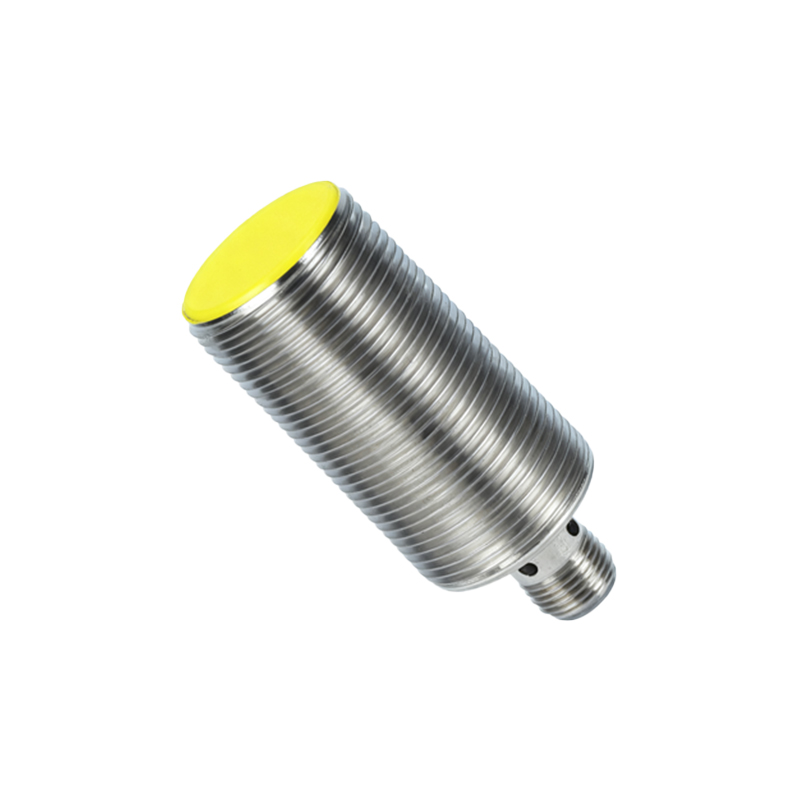
At the heart of these sensors lies a simple yet robust concept. The sensor itself, whether inductive, capacitive, or photoelectric, generates a control signal when a target enters its detection field. This signal is not used to energize a mechanical relay but to drive the base of an internal bipolar junction transistor (BJT). In a typical three-wire DC sensor, the three connections are: brown wire for DC positive supply (V+), blue wire for DC common (0V), and black wire for the switched output signal. The transistor acts as a solid-state switch for the load connected to the black wire. When the sensor is inactive (no target detected), the transistor is in a non-conducting state (cut-off). Upon detection, a small base current switches the transistor to a saturated, conducting state, effectively closing the circuit between the output wire and either the supply voltage or common line, depending on the transistor type.
NPN vs. PNP: Sinking and Sourcing Current
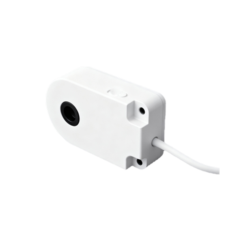
A critical distinction in sensor selection is between NPN and PNP output types, which define the current flow path. An NPN transistor output is configured as a sinking switch. In its active state, it connects the load to the common (0V) line. The load must be connected between the positive supply (V+) and the sensor's output wire. Conversely, a PNP transistor output is a sourcing switch. When active, it connects the load to the positive supply (V+). Here, the load is connected between the output wire and the common (0V). The choice between NPN and PNP is often dictated by the input circuit of the controlling device. Many PLCs from Europe and Asia are designed for PNP (sourcing) inputs, while NPN (sinking) is common in other regions. Understanding this polarity is paramount to correct system integration and avoiding potential damage.
Key Electrical Specifications and Ratings
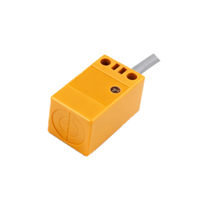
Selecting the appropriate sensor requires careful attention to its electrical ratings. The supply voltage range (e.g., 10-30 VDC) must be compatible with the available system power. The output current rating specifies the maximum continuous current the transistor can safely switch, typically ranging from 100mA to 500mA. Exceeding this rating can destroy the transistor. The leakage current is a small current (usually microamps) that may flow through the transistor when in the "off" state; this must be considered when connecting to high-impedance PLC inputs to prevent false triggering. Switching frequency indicates how many on/off cycles per second the sensor can handle, a crucial factor for high-speed counting or positioning applications. Finally, protection circuits like short-circuit, overload, reverse polarity, and surge protection are vital features that enhance sensor reliability in harsh electrical environments.
Wiring and Integration Practices
Correct wiring is essential for reliable operation. Always refer to the manufacturer's datasheet. For a three-wire DC sensor: connect the brown wire to V+, the blue wire to 0V, and the black output wire to the load (e.g., a PLC input terminal). The load's other terminal is then connected to complete the circuit based on the sensor type (NPN or PNP). A load resistor may be necessary if the connected device's input impedance is too high, ensuring sufficient current flow to register the state change. It is standard practice to install a fuse in the supply line for protection. For noise immunity in electrically noisy environments, use shielded cables, keep sensor cables away from power lines, and ensure proper grounding of the sensor housing and shield.
Advantages Over Other Output Types
Transistor outputs offer several compelling advantages. Their solid-state nature provides a virtually limitless mechanical life, as there are no moving contacts to wear out, unlike electromechanical relays. They enable much faster switching speeds, capable