Introduction to 4-Wire Photoelectric Sensors
A 4-wire photoelectric sensor is a versatile and widely used device in industrial automation for detecting the presence, absence, or position of objects. Unlike simpler 2-wire sensors, the 4-wire configuration provides separate paths for power supply and output switching, offering enhanced functionality and reliability. This design typically includes two wires for connecting to the DC power source (positive and negative) and two wires for the output signal (often a solid-state switch like a transistor). The independent output circuit allows for greater flexibility in connecting to various controllers, such as PLCs (Programmable Logic Controllers) or relays, without interfering with the power circuit. Understanding the correct wiring diagram is crucial for ensuring safe operation, optimal performance, and longevity of both the sensor and the connected control system. These sensors are commonly employed in packaging, material handling, assembly lines, and safety systems due to their high precision and fast response times.
Components and Terminal Identification
Before examining the wiring diagram, it is essential to identify the standard terminals on a 4-wire DC photoelectric sensor. The terminals are usually clearly labeled on the sensor housing or in the accompanying datasheet. The most common labeling convention is: Brown wire (or terminal marked +V, L+, or 1): This is the positive DC supply voltage wire. It must be connected to the positive terminal of the power source, typically ranging from 10-30 VDC. Blue wire (or terminal marked 0V, L-, COM, or 2): This is the negative DC supply voltage wire, or common. It must be connected to the negative terminal or ground of the power source. Black wire (or terminal marked OUT, NO, or 3): This is the output signal wire. For a normally open (NO) sensor, this wire will switch the load (e.g., PLC input) to the supply voltage when an object is detected. White wire (or terminal marked OUT, NC, or 4): This is often a second output wire, which may be configured as a normally closed (NC) output or a complementary output depending on the sensor model. Some sensors may have only one output wire (black) and use the blue wire as the common for both power and output. Always consult the manufacturer's specific wiring diagram, as colors and functions can vary (e.g., NPN vs. PNP output types).

Standard Wiring Diagram for NPN Output Type
The NPN output type, also known as sinking output, is a prevalent configuration. In this setup, the sensor's output transistor switches the negative (0V) side of the load. Here is a step-by-step wiring guide: First, connect the brown wire to the positive terminal (+V) of your DC power supply (e.g., 24 VDC). Second, connect the blue wire to the negative terminal (0V) of the same DC power supply. This completes the sensor's internal circuit, powering its electronics and LED. For the output, the black wire is the switched NPN output. Connect one side of your load (such as the input terminal of a PLC digital input module) to the positive supply voltage (+V). Connect the other side of the load to the black wire from the sensor. When the sensor detects an object, its internal NPN transistor activates, connecting the black wire to the blue wire (0V). This completes the circuit for the load, allowing current to flow from +V, through the load, through the sensor's transistor to 0V, thus signaling the PLC. The white wire, if present, may be unused or configured as a complementary output. Ensure the load's voltage and current ratings are within the sensor's specified limits.
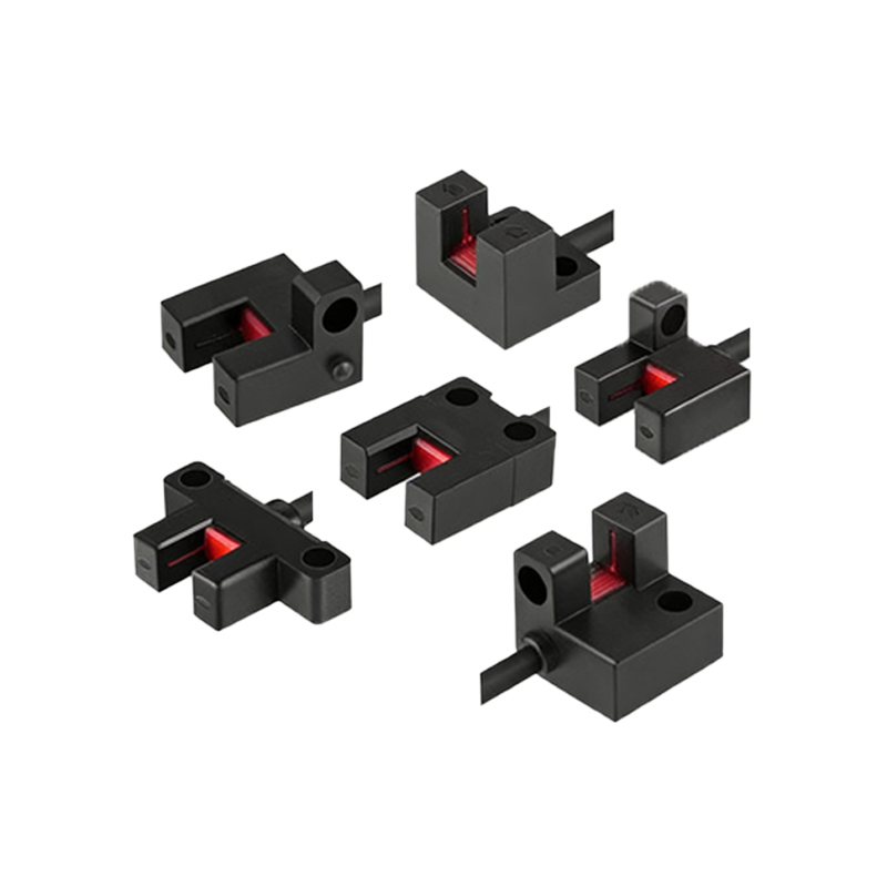
Standard Wiring Diagram for PNP Output Type
The PNP output type, also known as sourcing output, switches the positive side of the load. This configuration is equally common, especially in certain regional standards. The power connections remain identical: brown to +V and blue to 0V. The key difference lies in the output switching. For a PNP sensor, the black wire is the switched PNP output. Connect one side of your load (e.g., the PLC input) to the negative supply (0V or common). Connect the other side of the load directly to the black wire from the sensor. When the sensor detects an object, its internal PNP transistor activates, connecting the black wire internally to the brown wire (+V). This action applies the positive supply voltage to the load, completing the circuit from +V through the sensor, through the load, to 0V, thereby activating the PLC input. Again, the white wire may serve as an alternative NC output. Confusing NPN and PNP wiring is a common installation error that results in the sensor failing to trigger the control system.
Connecting to a PLC and External Devices
Integrating a 4-wire photoelectric sensor with a PLC is a fundamental task. The process depends on whether the PLC input module is designed for sinking (accepts PNP signals) or sourcing (accepts NPN signals). For a sinking PLC input (common to positive), you should use a PNP sensor. The sensor's black output wire connects to the PLC input terminal. The PLC input's common is internally tied to +V. For a sourcing PLC input (common to negative), you should use an NPN sensor. The sensor's black output wire connects to the PLC input terminal, and the PLC input's common is tied to 0V. Always include a protective fuse in the power supply line to the sensor and consider using shielded cables in electrically noisy environments, grounding the shield at one end. For connecting to relays or indicator lamps, ensure the sensor's output can handle the relay coil's inrush current, often by checking the maximum load current specification. Some applications may require an external pull-up or pull-down resistor, but modern sensors often have this built-in.
Common Troubleshooting and Safety Practices
Proper wiring is the first defense against operational issues. If a sensor fails to operate, first verify the power supply voltage at the brown and blue terminals with a multimeter. Ensure polarity is correct. Next, check the output. For an NPN sensor, measure voltage between the black wire and +V; it should be near supply voltage when off and near 0V when activated. For a PNP sensor, measure between black and 0V; it should be near 0V when off and near supply voltage when activated. Incorrect wiring can damage the sensor or the PLC input. Always disconnect power before making or changing connections. Adhere to electrical safety standards and lockout-tagout procedures. Ensure the sensor type (NPN/PNP) matches the connected load. Environmental factors like dust, moisture, or strong ambient light can also cause detection issues, so selecting the appropriate sensor housing and sensing mode (through-beam, retro-reflective, diffuse) is part of the initial design. Regularly inspect connections for corrosion or looseness.