Introduction to Mask Proximity Sensors
Proximity sensors have become an integral component in modern automated systems, and their application in mask detection and positioning is a critical area of development. A mask proximity sensor is a non-contact device designed to detect the presence or absence of a face mask within a specified range, typically triggering a subsequent action in a system. These sensors are pivotal in automated production lines for quality control, in access control systems for safety compliance, and in various smart devices. Unlike simple mechanical switches, proximity sensors offer reliability, longevity, and high-speed operation without physical wear and tear. Understanding their operational principles, types, and integration methods is essential for engineers designing systems that require precise, hygienic, and efficient mask handling or verification.
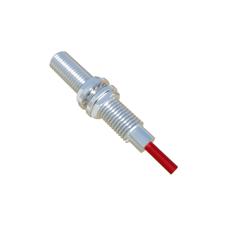
Core Operating Principles
The fundamental principle behind most mask proximity sensors is based on electromagnetic fields or optical beams. Inductive and capacitive sensors, which rely on changes in an electromagnetic field, are less common for mask detection unless the mask contains a metallic nose bridge wire. For typical non-woven fabric masks, optical sensors are predominantly used. These optical sensors operate by emitting a beam of light—often infrared (IR) to be invisible and immune to ambient light interference—and then measuring the reflected light. When a mask enters the detection zone, it reflects the emitted light back to the sensor's receiver. The sensor's internal circuitry processes this change in the received signal, converting it into a clear electrical output signal, typically a switch from high to low logic level or vice versa.
Primary Sensor Types and Selection Criteria
For mask detection, the main categories are diffuse reflective sensors and through-beam sensors. Diffuse reflective sensors house both the emitter and receiver in a single unit. They detect an object when the emitted light reflects off the mask's surface back to the receiver. Their effective range is limited and can be influenced by the mask's color and material reflectivity. Through-beam sensors consist of separate emitter and receiver units placed opposite each other. The mask is detected when it interrupts the light beam between them. This type offers longer detection ranges and higher reliability, as it is less affected by the object's surface properties. Selection depends on the application: diffuse sensors are suitable for compact spaces and direct mounting, while through-beam sensors are ideal for precise detection over longer distances or in conveyor belt setups.
Key Technical Specifications and Parameters
When selecting a sensor for a mask proximity application, several technical parameters must be carefully evaluated. The sensing distance, or range, is paramount. For diffuse sensors, this is the nominal sensing distance specified for a standard white surface, which may need derating for darker mask colors. The response time indicates how quickly the sensor can detect a change and update its output, crucial for high-speed production lines. The output type is another critical decision: NPN (sinking) or PNP (sourcing) transistor outputs are standard for connecting to Programmable Logic Controllers (PLCs) or microcontrollers. Environmental factors like ambient temperature, potential exposure to dust or moisture (requiring an appropriate IP rating), and the presence of other light sources must also be considered to ensure stable operation.
Circuit Design and Wiring Configuration
Integrating a proximity sensor into an electrical system requires a basic understanding of its wiring. A typical three-wire DC sensor will have connections for brown (V+), blue (V- or ground), and black (output signal). The power supply voltage must match the sensor's specifications, commonly 12-24V DC. The output wire connects to the input of a controller like a PLC. For an NPN sensor, the output acts as a switch to ground; the PLC input is pulled high internally and goes low when the sensor detects an object. For a PNP sensor, the output switches the positive voltage. Always include a protective fuse in the power line and, if necessary, a flyback diode for inductive loads controlled by the sensor output. Proper shielding of cables is recommended in electrically noisy industrial environments.
Installation, Alignment, and Calibration Tips
Correct installation is vital for reliable performance. Ensure the sensor is mounted securely to prevent vibration-induced errors. For through-beam sensors, precise alignment of the emitter and receiver is critical; a mounting bracket with adjustment screws can be invaluable. The sensor should be positioned so that the mask passes through the optimal point of its detection field. Avoid mounting near highly reflective backgrounds when using diffuse sensors, as this can cause false triggers. Most sensors feature a built-in LED indicator that lights up when an object is detected, which is extremely useful for initial setup and troubleshooting. Some advanced models offer teach-in functionality or potentiometers for fine-tuning sensitivity, allowing calibration to the specific reflectance of a mask material.