Understanding Tool Magazine Photoelectric Sensors
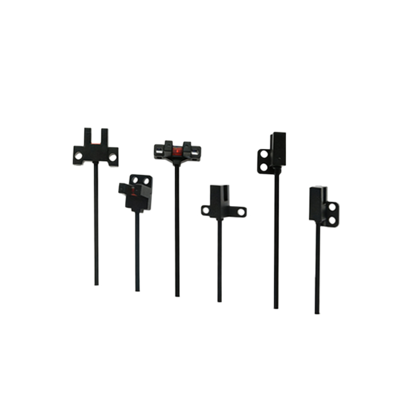
Tool magazine photoelectric sensors are critical components in automated machining centers, particularly in CNC (Computer Numerical Control) systems. These sensors function by emitting a light beam—typically infrared, red, or laser—and detecting its reflection or interruption to determine the presence, position, or status of tools within a magazine. The core principle relies on the modulation of light; a transmitter projects the beam, and a receiver analyzes the returned signal. In tool magazines, this technology ensures precise tool identification, prevents collisions, and maintains seamless tool change operations. Common types include through-beam, retro-reflective, and diffuse reflective sensors, each selected based on installation constraints, sensing distance, and environmental factors like coolant mist or metal chips.
Installation and Positioning Best Practices
Proper installation is paramount for reliable sensor performance. First, mount the sensor securely on the magazine structure, ensuring alignment between transmitter and receiver for through-beam types. Avoid mechanical vibrations or misalignment caused by machine movement. The sensing path must remain clear of obstructions such as cables, brackets, or accumulated debris. For retro-reflective sensors, position the reflector plate perpendicular to the beam axis to maximize signal strength. In environments with high contamination, consider sensors with built-in air blow ports or protective housings (IP67 or higher). Always verify the sensing distance margin—operating too close to the minimum or maximum range can lead to false triggers.
Wiring and Electrical Configuration
Photoelectric sensors in tool magazines typically interface with PLCs (Programmable Logic Controllers) or CNC controllers. Standard wiring involves connecting the sensor’s power supply (commonly 12-24V DC) and output signals (NPN or PNP transistor outputs). Shielded cables are recommended to minimize electrical noise from motors or drives. Configure the output mode based on application needs: light-on or dark-on operation determines whether the sensor activates when the beam is received or interrupted. For tool presence detection, a dark-on setup (output on when the beam is blocked by a tool) is often used. Additionally, many sensors feature teach-in functions or potentiometers for adjusting sensitivity, allowing fine-tuning to ignore background interference.
Application Scenarios in Tool Management
In practice, photoelectric sensors serve multiple roles within tool magazines. Primary applications include tool presence verification—ensuring a tool is correctly seated in its pocket before and after a change. Missing or misaligned tools can cause catastrophic damage, so sensors provide real-time feedback to halt operations if anomalies are detected. Another key use is position indexing; sensors detect notches or flags on rotary magazines to confirm angular alignment for tool selection. Additionally, they monitor magazine capacity by counting tools inserted or removed, aiding in predictive maintenance. Advanced systems employ multiple sensors for redundancy, coupled with RFID or barcode systems for tool identity tracking.
Troubleshooting Common Issues
Even with correct installation, sensors may encounter problems. Frequent issues include false signals due to ambient light interference—solve this by using modulated light sensors or installing sunshades. Contamination on lenses or reflectors reduces signal intensity; establish regular cleaning schedules using lint-free cloths and approved cleaners. Electrical problems like unstable power supply or ground loops can cause erratic behavior; check voltage levels and grounding connections. If a sensor fails intermittently, inspect cable integrity for damage or loose terminals. Many modern sensors feature diagnostic LEDs indicating power status, signal strength, or output activation, simplifying fault isolation. Always refer to the manufacturer’s manual for error codes and calibration procedures.
Maintenance and Longevity Tips
Routine maintenance extends sensor lifespan and ensures consistent accuracy. Schedule periodic inspections for physical damage, corrosion, or lens fouling. In harsh machining environments, clean sensors daily using compressed air or non-abrasive cleaners. Verify alignment annually, as thermal expansion or vibration may shift mounts over time. Keep spare sensors on hand to minimize downtime, and log performance data to identify wear patterns. When upgrading systems, consider sensors with higher ingress protection ratings or enhanced resistance to shock and temperature fluctuations. Training operators to recognize early warning signs—like delayed tool changes or inconsistent readings—can prevent major failures.
Integration with Industry 4.0 Systems
The evolution toward smart manufacturing integrates photoelectric sensors into IoT (Internet of Things) frameworks. Modern sensors with IO-Link or Ethernet/IP connectivity transmit real-time data to supervisory systems, enabling predictive analytics. For example, gradual signal degradation may indicate lens contamination, triggering automated alerts before a fault occurs. In digital twin models, sensor data replicates tool magazine behavior for simulation and optimization. Cybersecurity measures, such as network segmentation and encrypted communications, are essential when connecting sensors to cloud platforms. Ultimately, leveraging sensor data enhances overall equipment effectiveness (OEE) by reducing unplanned downtime and optimizing tool change cycles.