Understanding Photoelectric Sensor Basics
Photoelectric sensors are widely used in industrial automation for detecting the presence, absence, or distance of objects without physical contact. They operate by emitting a light beam (usually infrared, visible red, or laser) and measuring changes in the received light due to reflection, interruption, or beam convergence. Common types include through-beam, retro-reflective, and diffuse reflective sensors. Before installation, it's crucial to select the appropriate sensor type based on the application requirements, such as sensing range, environmental conditions (dust, moisture, ambient light), and object characteristics (color, material, size). Always refer to the manufacturer's datasheet for specifications like operating voltage, output type (PNP/NPN), and protection ratings (IP67 for dust/water resistance).
Pre-Installation Planning and Safety Measures
Proper planning ensures reliable sensor performance and longevity. Start by identifying the mounting location, considering factors like vibration, temperature extremes, and potential obstructions. Ensure the sensor and target object are aligned within the specified sensing range. Disconnect all power sources to the equipment before handling electrical components to prevent shocks or short circuits. Wear appropriate personal protective equipment (PPE), such as gloves and safety glasses, especially in harsh industrial environments. Gather necessary tools: a screwdriver, mounting brackets, cables, and conduit if needed. Verify that the sensor's electrical ratings match the control system's voltage and current requirements to avoid damage.
Step-by-Step Mounting and Alignment
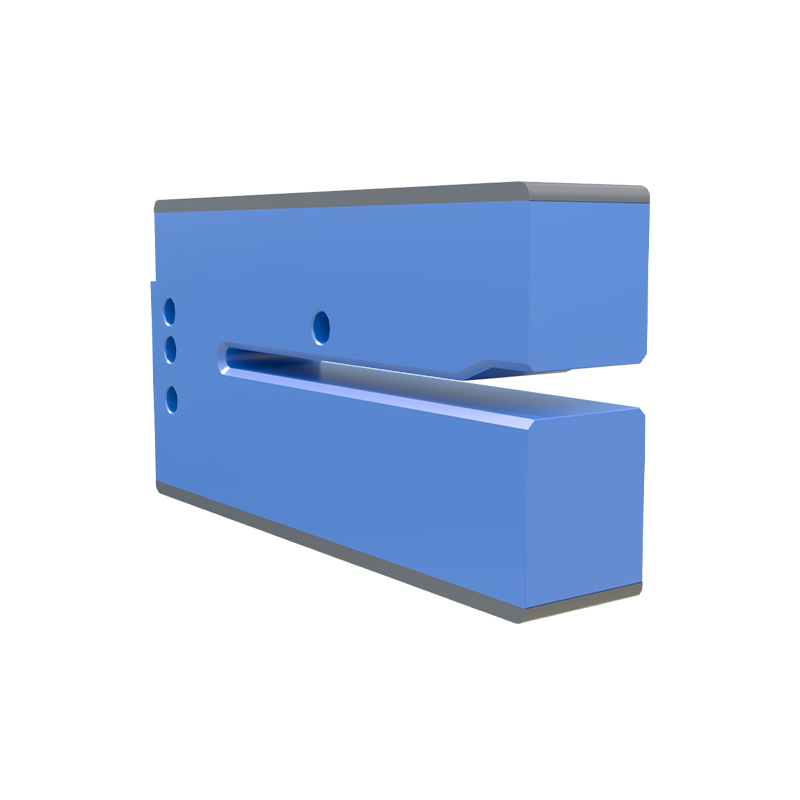
First, secure the sensor using the provided brackets or screws. For through-beam sensors, mount the emitter and receiver units opposite each other, ensuring they are firmly fixed to prevent misalignment from vibrations. Use a level tool to align both units parallel to each other. For retro-reflective sensors, position the sensor and reflector so that the light beam returns accurately; avoid angled surfaces that could deflect the beam. Diffuse sensors should be mounted at an optimal distance from the target, typically within the specified range. Adjust the sensor's angle if necessary, and tighten all fasteners to maintain stability. Image 1 below illustrates correct alignment for a through-beam setup, showing emitter and receiver on opposite sides of a conveyor belt.
Wiring and Electrical Connections
Connect the sensor to the power supply and control device (e.g., PLC) according to the wiring diagram in the manual. Typically, sensors have three or four wires: brown for positive voltage (+V), blue for negative or common (0V), black for output signal, and sometimes white for additional functions. Use shielded cables in electrically noisy environments to prevent interference. Strip the wire ends, insert them into the terminal blocks, and secure tightly to avoid loose connections. For PNP sensors, the output provides positive voltage when activated; NPN sensors sink current to ground. Double-check polarity to prevent reverse connection, which can damage the sensor. After wiring, organize cables with cable ties or conduits to reduce strain and exposure to hazards like moving parts.
Configuration and Sensitivity Adjustment
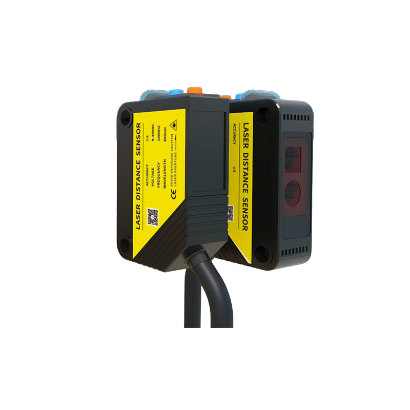
Many photoelectric sensors feature adjustable settings for sensitivity, response time, and operating mode. Locate the potentiometer or digital controls on the sensor housing. Turn on the power and observe the indicator LED: a steady light often means proper alignment, while a blinking light may indicate weak signal or misalignment. Adjust the sensitivity screw or button until the sensor reliably detects the target without false triggers from background objects. For challenging conditions (e.g., transparent materials or dark surfaces), use sensors with teach-in functionality to calibrate based on actual targets. Test the sensor by moving an object through its detection zone and verifying the output signal with a multimeter or PLC monitor. Image 2 demonstrates adjusting sensitivity on a diffuse sensor using a small screwdriver.
Testing and Troubleshooting Common Issues
After installation, conduct thorough testing under normal operating conditions. Check for consistent detection across various object positions and speeds. If the sensor fails to detect, first inspect alignment and clean lenses from dust or debris. Ensure the target is within the sensing range and reflects sufficient light (for reflective types). Electrical issues like no output may stem from incorrect wiring, insufficient voltage, or damaged cables—use a voltmeter to verify power and signal levels. Ambient light interference can be mitigated by using sensors with modulated light or installing shields. Regular maintenance, such as periodic cleaning and recalibration, helps sustain performance. Document the installation with photos for future reference, especially in complex setups.
Best Practices for Long-Term Performance
To maximize sensor lifespan, follow industry best practices. Choose sensors with robust housings (e.g., metal or high-grade plastic) for harsh environments. Implement redundancy for critical applications by using multiple sensors. Avoid mounting near strong magnetic fields or heat sources that could affect electronics. Keep firmware updated for smart sensors with digital interfaces. Train personnel on basic operation and troubleshooting to reduce downtime. Periodically review sensor performance logs and replace units showing signs of wear, such as faded lenses or erratic behavior. By adhering to these guidelines, photoelectric sensors can enhance automation efficiency with minimal failures.