Understanding the Core Issue: Load Capacity Mismatch
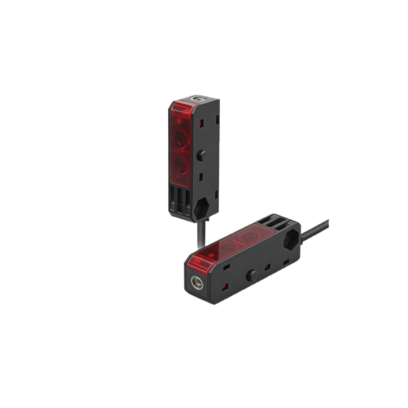
A common and frustrating challenge in industrial automation arises when a photoelectric sensor, seemingly functioning correctly, fails to activate an intermediate relay. The root cause is almost always a fundamental mismatch in electrical load capacity. Photoelectric sensors are designed as sensing devices, not power-switching units. Their solid-state output transistors (typically PNP or NPN) are engineered to handle relatively low currents, usually in the range of 100mA to 200mA. Intermediate relays, however, have coils that require a higher inrush current to energize the electromagnet and pull in the armature. This initial current surge can be two to three times the relay's nominal holding current. If the sensor's output cannot supply this peak current, the relay coil will not energize fully, resulting in a failure to switch.
Analyzing Output Types and Their Limitations
The type of sensor output is critical. A standard 3-wire DC sensor with a transistor output has clear current and voltage limits specified in its datasheet. Exceeding the maximum current will damage the sensor's internal switching element. Furthermore, the voltage drop across the output transistor (saturation voltage) when conducting reduces the actual voltage delivered to the relay coil. If the system voltage is 24VDC and the sensor has a 1.5V saturation drop, only 22.5V reaches the coil, which may be insufficient for reliable operation, especially in marginal conditions. Solid-state outputs also have leakage current when in the "OFF" state, which can sometimes be enough to partially energize a very sensitive relay coil, causing erratic behavior.
The Critical Role of Relay Coil Specifications
Engineers must pay meticulous attention to the relay coil specifications. Key parameters include the nominal operating voltage, coil resistance (or impedance for AC coils), and most importantly, the pull-in (or must-operate) voltage and current. The pull-in voltage is the minimum voltage required to reliably energize the coil from a de-energized state. It is often around 75-80% of the nominal voltage. If the sensor output cannot maintain voltage above this threshold under load, the relay will not switch. Additionally, the coil's inrush current demand must be compared directly against the sensor's maximum switching current rating.
Effective Solutions and Correct Wiring Practices
Several reliable solutions exist to resolve this incompatibility. The most straightforward is using an interposing device. A small, low-power relay or a solid-state relay (SSR) with a low input current requirement can be driven directly by the photoelectric sensor. This interposing device then handles the higher current load of the intermediate relay coil. Another solution is selecting a sensor with a relay contact output (mechanical or solid-state) rated for the necessary coil current. For DC systems, adding a freewheeling (flyback) diode across the relay coil is non-negotiable to protect the sensor's transistor from voltage spikes generated when the coil de-energizes. Proper wiring with adequate conductor size to minimize voltage drop is also essential.
Preventive Design and Component Selection Strategy
Prevention is superior to troubleshooting. During the design phase, adopt a systematic selection strategy. First, determine all electrical characteristics of the load (the intermediate relay coil). Then, select a sensor whose output specifications have a comfortable margin—aim for the sensor's continuous current rating to be at least 150% of the relay coil's nominal current. Consider the entire circuit's voltage drop, including wiring and connections. For critical applications, perform bench tests under worst-case conditions, such as minimum supply voltage and maximum ambient temperature. Utilizing manufacturer-provided technical support and application notes can prevent costly field failures and downtime.
Troubleshooting a Non-Functional Circuit
When faced with a non-operational circuit, follow a logical diagnostic procedure. First, verify power supply voltage at both the sensor and the relay with a multimeter. Second, check the sensor's operation independently by using a multimeter to measure its output voltage when activated, both under no-load and with the relay connected, to observe any significant voltage sag. Third, measure the actual current draw of the relay coil with the sensor in the circuit. If the sensor output voltage collapses when the relay is connected, it confirms an overload condition. Isolating the relay coil and testing it with a known good power source will verify its health. This step-by-step approach quickly identifies whether the fault lies with the sensor's capacity, the relay coil, or the wiring.