Introduction to Proximity Switch Sensor Measurement
Proximity switch sensors are indispensable components in modern industrial automation, particularly for length measurement or "metering" applications. These non-contact sensors detect the presence or absence of a target object, generating a pulse for each detection event. By counting these pulses as a material—such as wire, cable, textile, or sheet metal—passes by, a system can calculate the total length processed. The fundamental formula is straightforward: Length = (Pulse Count × Circumference of Measuring Wheel) / Number of Targets per Revolution. Despite the apparent simplicity, achieving and maintaining high accuracy in real-world production environments presents significant engineering challenges. Even minor errors can accumulate, leading to substantial material waste, production inefficiencies, and cost overruns over time.
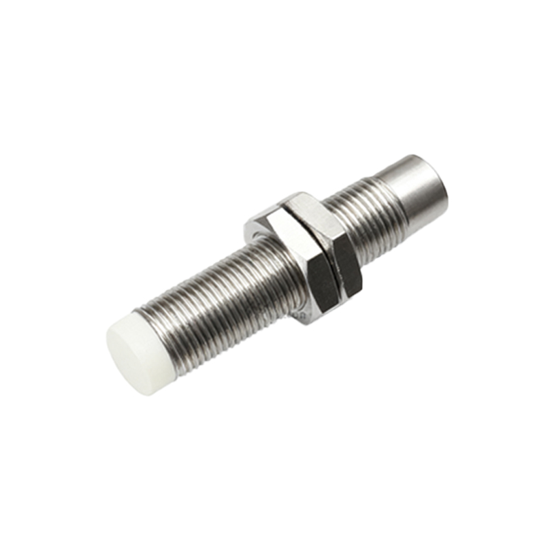
Primary Sources of Measurement Error
Several key factors contribute to inaccuracies in proximity sensor-based metering systems. The most common source is slippage between the measuring wheel and the material being measured. If the material slips or skids, the wheel's rotation no longer perfectly corresponds to the linear travel of the material, causing a direct error. The material's tension, surface texture, and the wheel's pressure and wear condition all influence slippage. Another critical factor is mechanical tolerances and wear. The measuring wheel's diameter can change due to thermal expansion, abrasive wear from the material, or even pressure deformation. A change of just 0.1mm in diameter can result in a measurable error over long lengths. Furthermore, sensor mounting and alignment issues can cause missed counts or false triggers, especially at high speeds.
Sensor Selection and Signal Integrity
The choice of proximity sensor itself is paramount. Inductive sensors are common for metallic targets, while capacitive sensors may be used for other materials. Key specifications include switching frequency, repeat accuracy, and hysteresis. A sensor with an insufficient switching frequency may fail to register pulses when the target passes at high speed, leading to under-counting. Signal bounce or noise can cause multiple false counts from a single target. Ensuring clean, shielded cabling, proper grounding, and using sensors with built-in noise immunity are essential steps. The sensor should be paired with a high-quality counter or PLC input module capable of reliably processing fast, clean pulses without missing edges.
Mechanical Design and Calibration Best Practices
Superior mechanical design is the foundation of accurate measurement. The measuring wheel should be manufactured from a durable, dimensionally stable material with a high-friction coating to minimize slippage. It must be mounted on precision bearings to reduce rotational resistance and runout. Implementing a spring-loaded or pneumatic tensioning system ensures consistent contact pressure, adapting to variations in material thickness. Regular calibration is non-negotiable. A master length of material should be measured through the system, and a correction factor (K-factor) should be applied in the control software to compensate for systematic error. This calibration must be repeated periodically and whenever components are changed or significant wear is suspected.
Environmental and Operational Influences
The operating environment significantly impacts accuracy. Temperature fluctuations affect the dimensions of the measuring wheel, the sensor's characteristics, and even the material itself. Dust, oil, or debris buildup on the wheel or sensor face can alter the effective diameter or detection reliability. Vibrations from other machinery can loosen mounts or cause intermittent signal loss. For critical applications, environmental controls or compensatory algorithms may be necessary. Operational factors like sudden changes in line speed, material jitter, or inconsistent material properties (e.g., thickness variations) also introduce dynamic errors that static calibration cannot fully address.
Advanced Compensation Techniques and System Integration
To push accuracy to higher levels, advanced techniques are employed. Dual-sensor systems with quadrature encoding can determine direction and provide a degree of slippage detection. Integrating an encoder directly on the motor drive or an un-winding spindle provides a reference speed that can be compared to the measuring wheel speed, allowing for real-time slippage compensation. Modern PLCs and dedicated measuring controllers can use this data to dynamically adjust the effective diameter or pulse count. Data logging and trend analysis help identify gradual wear or process drift before it results in unacceptable error, enabling predictive maintenance.
Conclusion and Continuous Improvement
Achieving minimal error in proximity sensor-based length counting is not a one-time setup but a continuous process of selection, design, calibration, and monitoring. Engineers must adopt a holistic system view, considering the interplay between mechanical, electrical, and software components. By understanding the root causes of error—slippage, mechanical wear, signal issues, and environmental effects—and implementing robust design principles alongside regular maintenance and calibration protocols, measurement accuracy can be consistently maintained within tight tolerances. This diligence ensures