Introduction to Photoelectric Sensing Fundamentals
Photoelectric sensors are ubiquitous in industrial automation, offering non-contact detection of objects based on the modulation of a light beam. At their core, these devices function by employing a light emitter, a receiver, and sophisticated electronic circuitry to interpret the received signal. The performance, reliability, and application suitability of a photoelectric sensor are fundamentally determined by the quality and configuration of its internal electronic components. Understanding these components is not merely an academic exercise; it is essential for selecting the right sensor, troubleshooting system failures, and designing robust automation solutions. This guide delves into the critical circuit components that form the backbone of modern photoelectric sensors, explaining their function and impact on overall system performance.
The Light Emitting Diode (LED) and Driver Circuit
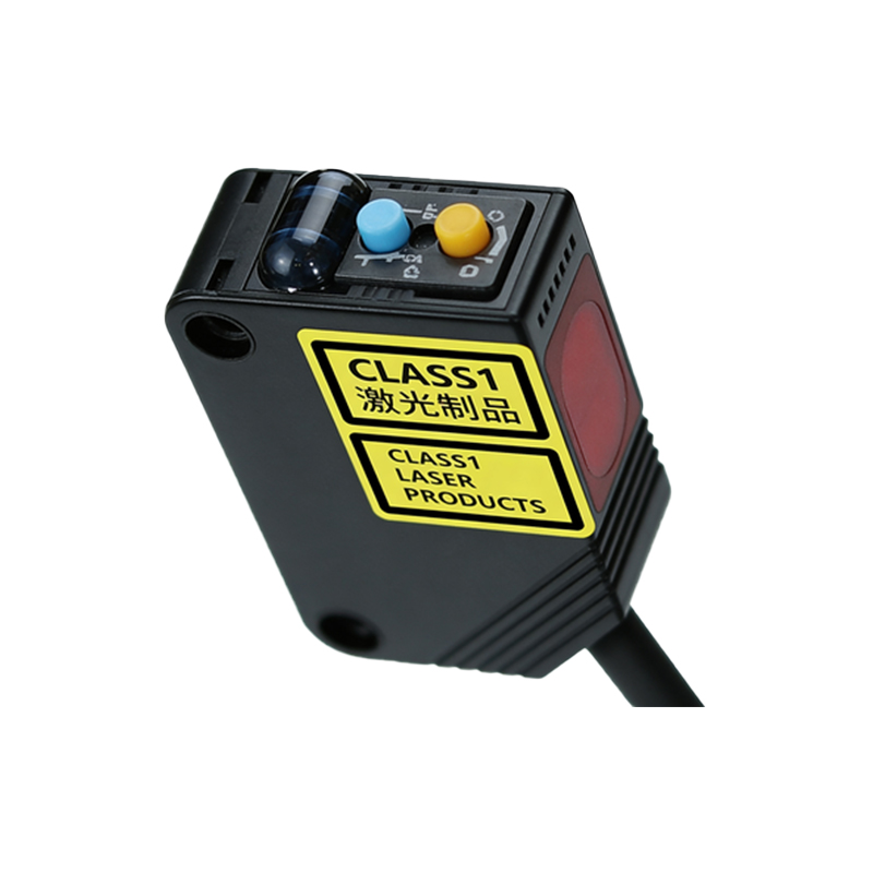
The light source in most contemporary photoelectric sensors is a Light Emitting Diode (LED). LEDs are favored for their long life, low heat generation, fast response times, and ability to be modulated at high frequencies. The specific wavelength—infrared, red, or laser—is chosen based on the application's requirements for visibility, sensing distance, and environmental interference. The LED does not operate in isolation; it is driven by a dedicated driver circuit. This circuit typically includes a current-limiting resistor or a more complex constant-current source to ensure the LED receives a stable, precise current. This stability is crucial for maintaining consistent light output intensity, which directly affects the sensor's signal-to-noise ratio and long-term repeatability. In pulsed-modulation systems, the driver circuit rapidly switches the LED on and off at a specific frequency, a technique that greatly enhances immunity to ambient light.
Photodetector: Phototransistor vs. Photodiode
The receiver's heart is the photodetector, which converts incoming light photons back into an electrical current. The two most common types are the photodiode and the phototransistor. Photodiodes offer very fast response times and excellent linearity but produce a relatively small output current (photocurrent). Phototransistors incorporate a gain stage, providing a much larger output current for a given light intensity, which simplifies subsequent amplification but can be slightly slower. The choice between them involves a trade-off between speed, sensitivity, and circuit complexity. The photodetector is always paired with a spectral filter, often integrated into its package, to block unwanted wavelengths of ambient light and ensure it primarily responds to the wavelength emitted by the paired LED, enhancing noise immunity.
The Amplifier and Signal Conditioning Stage
The minute electrical signal from the photodetector is far too weak to be processed directly. It is fed into a signal conditioning stage, which almost always begins with a transimpedance amplifier (TIA). A TIA converts the photodetector's current signal into a more usable voltage signal. The gain and bandwidth of this amplifier are critical design parameters. Following initial amplification, the signal passes through filters. A band-pass filter is commonly used to isolate the specific modulation frequency of the emitted light, effectively rejecting DC components from constant ambient light and high-frequency electrical noise. This stage is where the sensor's immunity to optical and electrical interference is largely determined. High-quality components here result in a clean, stable signal for the decision-making logic.
Comparator and Output Circuitry
The conditioned analog voltage signal is then compared to a predefined threshold voltage by a component called a comparator. This threshold is often user-adjustable via a potentiometer or digital interface, allowing for sensitivity calibration. When the incoming signal exceeds this threshold (indicating the presence or absence of an object, depending on the sensing mode), the comparator's digital output switches state. This digital signal then drives the output circuitry. For solid-state outputs like NPN/PNP transistors, the output stage includes protection components such as flyback diodes and current-limiting resistors to safeguard against inductive loads and short circuits. For relay outputs, a driver circuit energizes the relay coil. The robustness of the output stage defines the sensor's ability to interface directly with Programmable Logic Controllers (PLCs), motor starters, and other industrial loads.
Power Supply Regulation and Protection
A reliable internal power supply is non-negotiable. Most industrial photoelectric sensors operate on a wide range of DC voltages (e.g., 10-30 VDC). A voltage regulator IC ensures that the sensitive analog and digital components receive a stable, clean voltage (e.g., 5V or 3.3V) regardless of input voltage fluctuations or noise on the supply lines. This section also incorporates essential protection components: reverse-polarity protection diodes, fuses or polyfuses, and transient voltage suppression (TVS) diodes. These elements protect the sensor from common installation errors and harsh electrical environments, such as voltage spikes from solenoids or motors, significantly enhancing the sensor's longevity and field reliability.
Advanced Components: Microcontrollers and Communication Interfaces
In smart sensors and units with advanced functions like background suppression, precise distance measurement, or IO-Link communication, a microcontroller unit (MCU) is the central brain. The MCU manages LED modulation patterns, processes digitized sensor signals with algorithms, handles user interface commands (like button presses or teach-in functions), and manages data communication. For sensors with IO-Link capability, additional interface ICs are present to handle the physical layer communication protocol, enabling bidirectional data exchange for parameter setting, condition monitoring, and advanced diagnostics. These components transform a simple presence detector into an intelligent node on the industrial network.
Conclusion: The Synergy of Components
The operational excellence of a photoelectric sensor emerges from the precise interaction of all its circuit components. From the stable emission of the LED driver to the noise-resistant signal conditioning, the decisive action of the comparator, and the robust output stage, each part plays a vital role. For the engineering professional, a deep understanding of these components facilitates informed sensor selection, enables effective diagnostic procedures when a sensor malfunctions, and provides the insight needed to integrate these devices into fail-safe automation systems. As sensor technology evolves towards greater intelligence and connectivity, the foundational principles of these core electronic components remain as relevant as ever.