Introduction to Inductive Proximity Sensors
Inductive proximity switches are fundamental components in modern industrial automation, renowned for their robustness, non-contact operation, and reliability. These sensors detect the presence or absence of metallic objects without any physical contact, making them ideal for harsh environments where dirt, oil, or vibration are prevalent. Operating on the principle of electromagnetic induction, they generate an oscillating electromagnetic field from a coil housed within the sensor's face. When a conductive metal target enters this field, eddy currents are induced on the target's surface. This causes a change in the oscillation amplitude within the sensor, which is then processed by an internal circuit to trigger a solid-state output signal. This simple yet effective mechanism underpins their widespread use across countless manufacturing and processing applications.
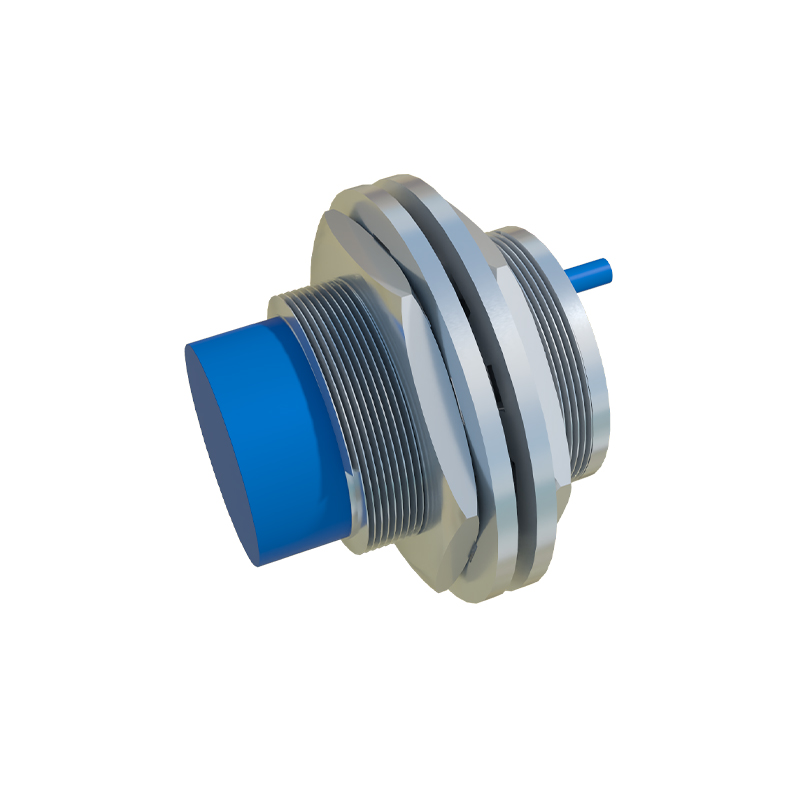
Core Operating Principles and Key Characteristics
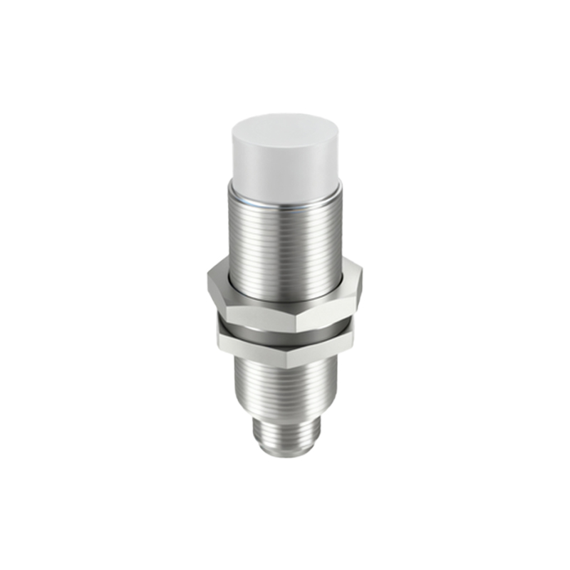
The heart of an inductive proximity sensor is its oscillator, coil, and detection circuit. The oscillator generates a high-frequency electromagnetic field that radiates from the active surface. The key characteristic is that only electrically conductive materials, primarily metals, can disturb this field. The sensing distance, or 'switching distance,' is a critical specification and is standardized as the 'nominal sensing distance (Sn).' It is important to note that this distance can vary depending on the target material's properties; for instance, steel is detected at 100% of Sn, while stainless steel might be detected at 85%, and aluminum or copper at significantly less, often 30-40%. This factor, known as the reduction factor, is crucial for correct application. These sensors are also characterized by their high switching frequency, immunity to environmental contaminants, and long operational life due to the absence of moving parts.
Common Types and Output Configurations
Inductive proximity sensors are available in several form factors and electronic configurations to suit diverse needs. The most common housing styles include cylindrical barrels (e.g., M8, M12, M18, M30 threaded barrels), rectangular or block-style housings, and ring-shaped sensors for detecting small parts. In terms of output, they are predominantly solid-state. Two-wire AC/DC sensors are simple to wire but have a residual current when off. Three-wire DC sensors are the most prevalent, offering either a PNP (sourcing) or NPN (sinking) transistor output, which must be matched to the controller's input type (e.g., PLC). Four-wire versions provide both a normally open (NO) and normally closed (NC) output in one device. Additionally, analog output versions provide a continuous signal proportional to the distance to the target, useful for positioning applications.
Primary Industrial Applications
The applications for inductive proximity switches are virtually limitless in automation. They are extensively used for object detection on conveyor lines, such as counting bottles, detecting metal parts, or verifying the presence of components. In machine tools, they serve as end-of-travel limit switches for axes, tool breakage detection, and part clamping verification. They are essential in material handling for pallet positioning, crane hook height control, and door open/close status. In the automotive industry, they monitor robotic weld gun positions and detect fixtures. Their sealed designs (often IP67 or IP69K) make them perfect for washdown areas in food and beverage or pharmaceutical plants. Essentially, anywhere reliable, non-contact detection of metal is required, an inductive sensor is a prime candidate.
Critical Selection Criteria for Engineers
Selecting the correct inductive sensor requires careful consideration of several parameters. First, define the target material and required sensing distance, applying the appropriate reduction factor. Next, choose the housing style and size based on available mounting space. The electrical requirements are paramount: operating voltage (commonly 10-30V DC or 20-250V AC), output type (PNP/NPN, NO/NC), and current rating. Environmental factors like temperature range, required ingress protection (IP rating), and potential exposure to chemicals or welding spatter must be evaluated. For high-speed applications, ensure the sensor's response frequency exceeds the required detection rate. Finally, consider special features like short-circuit protection, reverse polarity protection, and embedded diagnostic LEDs, which aid in installation and troubleshooting.
Installation Best Practices and Troubleshooting
Proper installation is key to optimal performance. A primary consideration is maintaining the correct installation geometry. Sensors should be mounted so that only the intended target approaches the active sensing face. Installing a cylindrical sensor too close to a metal mounting bracket can cause a parasitic damping effect, reducing the effective sensing range. Always observe the manufacturer's specified flush-mounting or non-flush-mounting guidelines. Ensure wiring is correct according to the datasheet, paying close attention to polarity for DC