Introduction to Proximity Switches with Magnetic Actuation
Proximity switches are indispensable components in industrial automation, providing non-contact detection of metallic objects. Among various types, inductive proximity sensors are most common. However, integrating permanent magnets into the sensing system or utilizing magnetically actuated proximity switches introduces unique applications and wiring considerations. These setups are particularly valuable in environments requiring detection through non-metallic barriers, in harsh conditions, or for specific positional sensing where standard inductive sensing falls short. Understanding the correct wiring methodology for proximity sensors used in conjunction with magnets is crucial for ensuring system reliability, safety, and optimal performance. This guide delves into the technical specifics, wiring diagrams, and best practices for engineers.
Fundamental Operating Principles
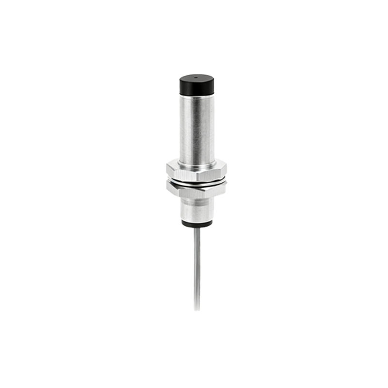
A standard inductive proximity sensor generates an electromagnetic field. When a ferrous metal target enters this field, it causes a change in oscillation amplitude, which the sensor's circuit detects, triggering a switching action. When a permanent magnet is involved, the principle can differ. One common application is using a magnet as the "target" for a specially designed sensor, often a reed switch-based or Hall-effect proximity sensor. These sensors detect the presence of the magnetic field itself, not just conductive metal. Another application involves using a magnet to actuate a mechanical element (like a plunger) in a magnetically operated limit switch, which then changes the state of internal electrical contacts. The wiring for the sensor itself, however, often follows standard conventions regardless of the actuation method.
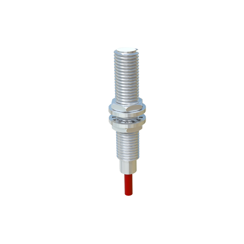
Standard Wiring Configurations and Terminals
Most industrial proximity sensors, including those designed for magnetic actuation, come in three primary wiring types: 2-wire AC/DC, 3-wire DC, and 4-wire DC. The 3-wire DC sensor is the most prevalent. Its terminals are typically labeled as Brown (or +V), Blue (or 0V/Common), and Black (or Switched Output). For a PNP (sourcing) sensor, the black wire provides a positive voltage to the load when the target (magnet) is detected. For an NPN (sinking) sensor, the black wire provides a path to ground. It is critical to confirm the sensor's datasheet specifications—whether it's designed for dry contact switching (like in a magnetically actuated limit switch) or solid-state electronic switching (like a Hall-effect sensor). Miswiring can lead to sensor damage or improper PLC input response.
Specific Wiring for Hall-Effect and Reed Sensors
Proximity sensors that directly detect a magnet's field, such as Hall-effect or reed sensor-based units, are typically 3-wire DC devices. Wiring a Hall-effect sensor requires connecting its Vcc (power supply, e.g., +12V or +24V DC) to the brown wire, its ground to the blue wire, and its output signal line to the black wire. The output is usually digital (on/off). A pull-up or pull-down resistor might be necessary depending on the output configuration and the PLC input module type. Reed sensors, often used in lower-power or sealed applications, may be two-wire devices that act as a dry contact. They are wired in series with the load and power supply, functioning like a simple switch that closes when the magnet is present.
Integration with Control Systems and PLCs
Connecting a magnetically actuated proximity switch to a Programmable Logic Controller (PLC) is a standard practice. For a 3-wire PNP sensor, the brown wire connects to the DC positive supply, the blue wire to the DC negative/0V, and the black wire to the designated PLC digital input. The PLC input common is typically connected to 0V. For an NPN sensor, the black wire connects to the PLC input, and the PLC input's common must be connected to the positive supply; this completes the sinking current path. Always ensure the sensor's voltage rating matches the PLC supply voltage. Proper shielding and routing of cables away from power lines are essential to prevent electromagnetic interference, which can be exacerbated by strong magnetic fields in the vicinity.
Installation Considerations and Magnetic Interference
A key challenge when using magnets is managing magnetic interference. Strong external magnetic fields can falsely trigger or inhibit a magnetic field-sensitive sensor like a Hall-effect or reed type. Therefore, installation must maintain adequate distance from motors, transformers, and other sources of electromagnetic fields. When the magnet is used as a target, the sensing distance is significantly reduced compared to a standard ferrous metal target for an inductive sensor. The orientation of the magnet's poles relative to the sensor is also critical; the datasheet will specify the optimal orientation (e