Introduction to Optical Fiber Photoelectric Sensors
Optical fiber photoelectric sensors represent a critical technology in modern industrial automation and measurement systems. These sensors utilize the principle of light modulation through optical fibers to detect various physical parameters such as displacement, pressure, temperature, and presence of objects. The core mechanism involves transmitting light from a source through an optical fiber to a sensing point, where the light interacts with the target. Changes in the light's intensity, phase, or wavelength are then captured and converted into electrical signals for analysis. This technology offers significant advantages over traditional sensors, including immunity to electromagnetic interference, high sensitivity, and the ability to operate in harsh environments. For electrical engineers, understanding the experimental setup and operation of these sensors is essential for applications in robotics, manufacturing, and safety systems. The following sections provide a detailed guide to conducting a basic experiment with optical fiber photoelectric sensors, covering components, procedures, and data interpretation.
Experimental Components and Setup
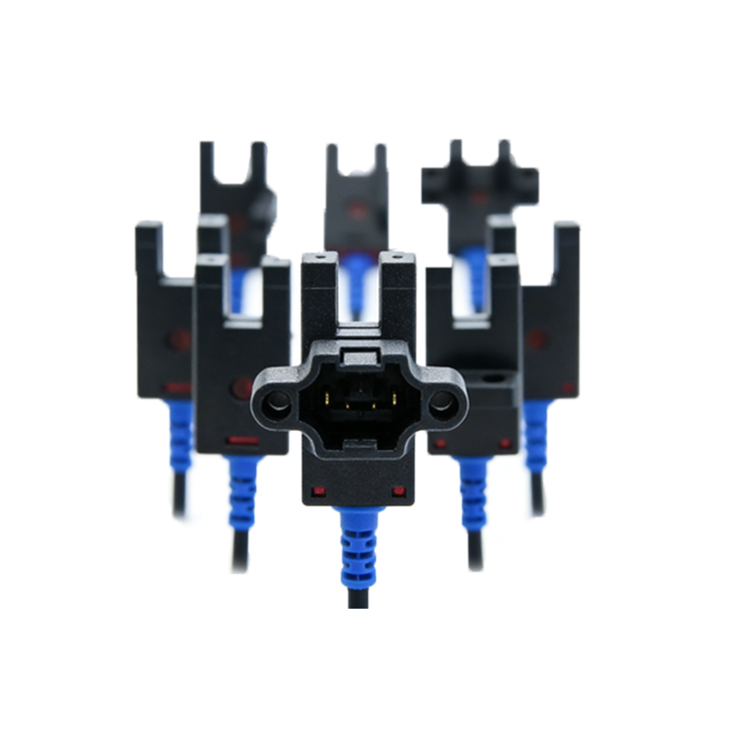
A typical optical fiber photoelectric sensor experiment requires several key components to ensure accurate and reliable results. First, a light source, such as a laser diode or LED, generates the optical signal. This source is connected to a transmitter optical fiber, which guides the light to the sensing region. The sensor head, often a reflective or through-beam type, is positioned to interact with the target object. A receiver optical fiber collects the modulated light and directs it to a photodetector, like a photodiode or phototransistor, which converts the optical signal into an electrical current. This current is then amplified and processed by a signal conditioning circuit, including amplifiers and filters, to enhance the signal-to-noise ratio. Finally, a data acquisition system, such as an oscilloscope or microcontroller, records and analyzes the output. The setup must be carefully aligned on an optical bench to minimize losses, with fibers securely connected using connectors like FC or ST types. Proper calibration using standard targets is crucial before proceeding with measurements to establish baseline readings.
Step-by-Step Experimental Procedure
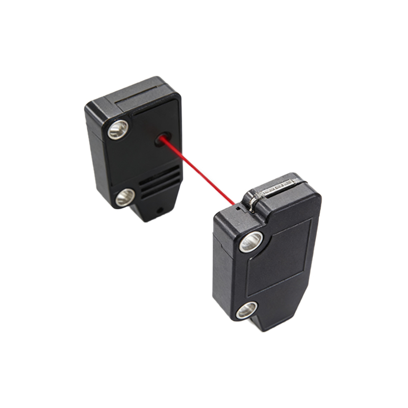
Begin the experiment by assembling the components on a stable optical table in a controlled environment to reduce external vibrations and light interference. Connect the light source to the transmitter fiber using appropriate connectors, ensuring the fiber ends are clean to prevent signal attenuation. Position the sensor head at a fixed distance from the target, typically a reflective surface or an opaque object, depending on the sensor type. For a reflective sensor, align the transmitter and receiver fibers at an optimal angle to maximize light reflection. Power on the light source and adjust its intensity to a suitable level, avoiding saturation of the photodetector. Next, activate the signal conditioning circuit and data acquisition system, setting parameters like sampling rate and gain based on the expected signal range. Move the target gradually through the sensing field, recording changes in the output voltage or current as the light modulation occurs. Repeat the process for different target materials, distances, and environmental conditions to observe variations in sensor response. Document all steps meticulously, noting any deviations or anomalies for later analysis.
Data Analysis and Interpretation
After collecting experimental data, analyze the results to evaluate sensor performance. Plot the output signal against target displacement or other variables to create characteristic curves, such as sensitivity graphs or hysteresis loops. Calculate key metrics like resolution, which is the smallest detectable change in the target position, and linearity, indicating how well the sensor output correlates with input changes over its range. Use statistical tools to assess repeatability and accuracy by comparing multiple trials. For instance, if the sensor shows nonlinear behavior at extreme distances, consider adjusting the optical alignment or signal processing parameters. Discuss potential sources of error, such as fiber bending losses, ambient light interference, or temperature fluctuations, and propose mitigation strategies. This analysis helps engineers optimize sensor design for specific applications, such as precision alignment in semiconductor manufacturing or object detection in automated assembly lines. Include sample calculations and graphs in the report to illustrate findings clearly.
Applications and Future Trends
Optical fiber photoelectric sensors are widely used across various industries due to their versatility and robustness. In automotive manufacturing, they enable non-contact measurement of part dimensions and quality control. In aerospace, they monitor structural health by detecting strain or cracks in composite materials. The medical field employs them in minimally invasive surgical tools for precise positioning. Looking ahead, advancements in materials science and nanotechnology are driving the development of smarter sensors with integrated AI capabilities for real-time data processing. Trends include the use of multi-core fibers for distributed sensing and the integration with IoT systems for remote monitoring. Engineers should stay updated on these innovations to leverage optical fiber sensors in emerging fields like renewable energy and smart cities. This experiment serves as a foundation for exploring more complex setups, such as multiplexed sensor networks or fiber Bragg grating systems.
Conclusion and Best Practices
Conducting an optical fiber photoelectric sensor experiment provides hands-on insight into a vital technology for electrical engineering. Key takeaways include the importance of precise alignment, proper calibration, and thorough data analysis to achieve reliable measurements. Always use high-quality optical components and maintain clean fiber connections to minimize signal loss. When designing sensor systems, consider environmental factors and choose sensor types—reflective, through-beam, or diffuse—based on application requirements. Regularly update knowledge through industry publications and conferences to incorporate the latest advancements. By mastering these experimental techniques, engineers can contribute to innovative solutions in automation, safety, and beyond, ensuring efficient and accurate sensing in diverse operational contexts.