Understanding 8mm Proximity Sensor Fundamentals
An 8mm proximity sensor is a compact, non-contact sensing device widely used in industrial automation for detecting the presence or absence of metallic objects within its nominal sensing range. These cylindrical sensors, typically in a threaded barrel style, operate on the principle of electromagnetic induction (for inductive types) or capacitive/ultrasonic principles for other variants. The 8mm designation refers to the sensor's body diameter, making it ideal for space-constrained applications. Before commencing any wiring procedure, it is paramount to consult the specific sensor's datasheet. Critical parameters include the operating voltage (commonly 10-30V DC or 90-250V AC), output type (NPN sinking, PNP sourcing, or NO/NC contacts), and current rating. Misidentification of these specifications is a primary cause of sensor failure or circuit damage.
Essential Tools and Safety Precautions
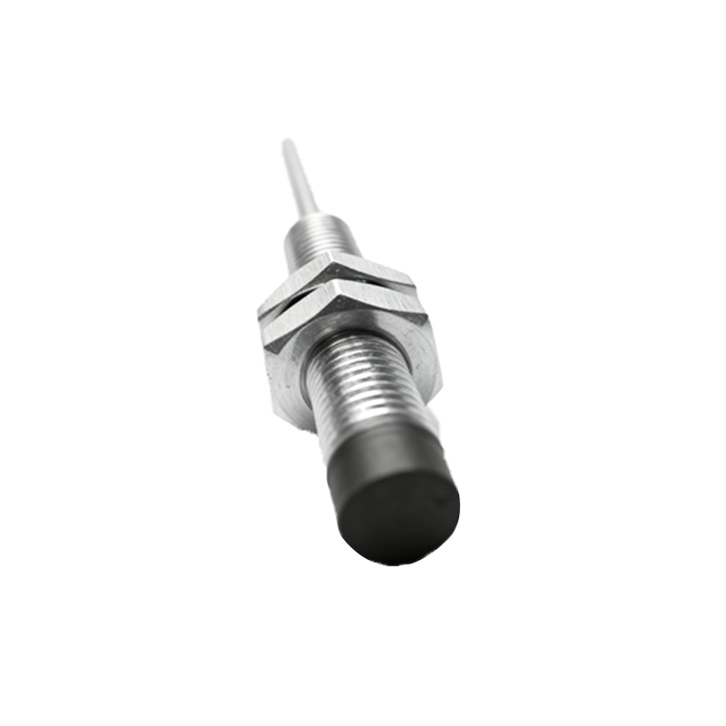
Gather all necessary tools and materials before starting. You will typically need a screwdriver set, wire strippers, crimping tools, appropriate gauge electrical wires (often 18-22 AWG shielded cable is recommended for noise immunity), and terminal connectors. Always adhere to fundamental electrical safety protocols. Disconnect and lock out all power sources to the control circuit. Verify the absence of voltage using a multimeter. Wear appropriate personal protective equipment (PPE). Ensure the work environment is clean and dry to prevent short circuits or corrosion. Proper planning and safety measures prevent accidents and ensure a durable installation.
Identifying Sensor Wire Color Codes and Functions
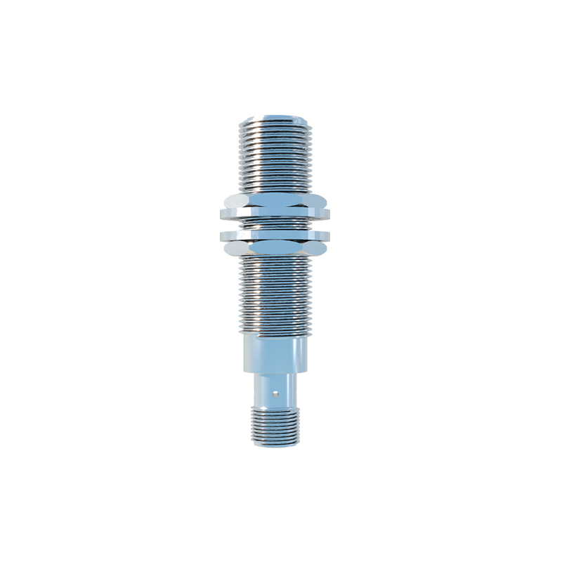
Most 3-wire DC 8mm proximity sensors follow a standard color-coding scheme, though variations exist. The most common configuration is: Brown wire for positive DC supply voltage (+V), Blue wire for negative DC supply voltage (0V or common), and Black wire for the output signal. For a 2-wire AC/DC sensor, the two wires are typically interchangeable and connect in series with the load. A 4-wire sensor often includes two output channels (e.g., one NPN and one PNP, or a NO and NC contact). The sensor's housing or datasheet will explicitly label the function of each wire. Never assume wire functions based on color alone; always cross-reference with the manufacturer's documentation.
Wiring a 3-Wire DC NPN Proximity Sensor
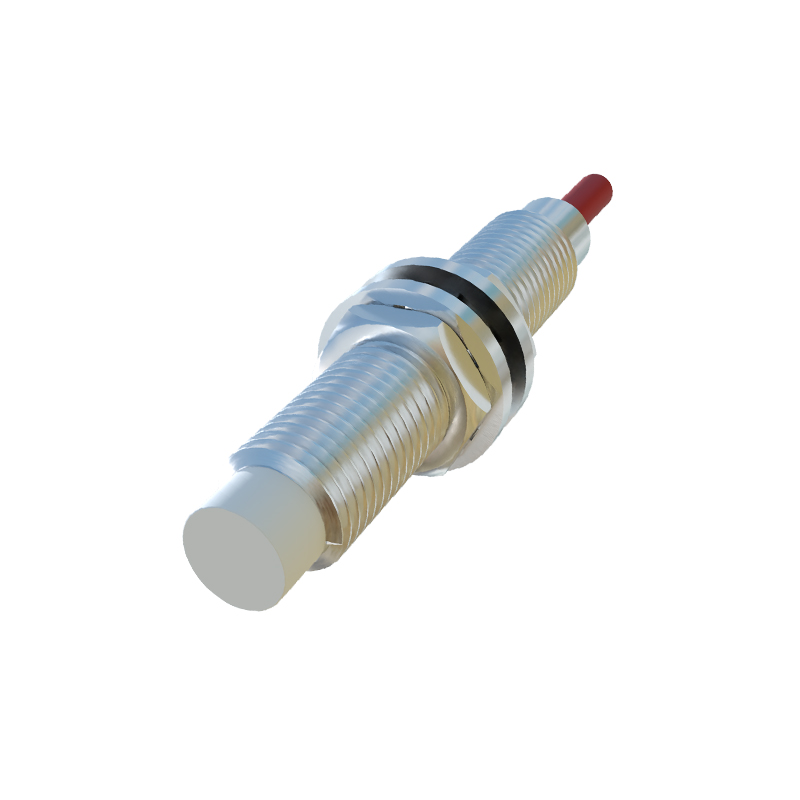
The NPN type is a sinking output sensor. In this configuration, the output switch (black wire) is connected internally to the negative supply (blue wire). To wire it: First, connect the brown wire to the positive terminal of your DC power supply (e.g., +24V). Second, connect the blue wire to the negative terminal (0V) of the same power supply. Finally, connect the black (output) wire to one side of your load (e.g., a PLC input module, relay coil, or indicator lamp). The other side of the load must then be connected to the positive supply rail. When the sensor activates, it "sinks" current from the load to ground, completing the circuit and switching the load ON.
Wiring a 3-Wire DC PNP Proximity Sensor
The PNP type is a sourcing output sensor. Here, the output switch (black wire) is connected internally to the positive supply (brown wire). The wiring sequence is: Connect the brown wire to the positive DC supply (+V). Connect the blue wire to the negative DC supply (0V). Connect the black (output) wire to one side of your load. Crucially, the other side of the load must now be connected to the negative supply rail (0V). Upon activation, the sensor "sources" current from the positive supply through the load to ground, thereby energizing the load. Confusing NPN and PNP wiring is a frequent error that results in the load not operating.
Connecting to a Programmable Logic Controller (PLC)
Integrating an 8mm sensor with a PLC is a common task. For a DC input module, determine if the module is designed for sinking (common +V) or sourcing (common 0V) inputs. Match your sensor type accordingly. For a sinking input PLC module (common +24V), you must use a PNP sensor. The sensor's black wire connects to the PLC input terminal, and the blue wire connects to the PLC's common (0V). For a sourcing input PLC module (common 0V), you must use an NPN sensor. The sensor's black wire connects to the PLC input, and the brown wire connects to the PLC's common (+24V). Always include a