Understanding Through-Beam Photoelectric Sensors
Through-beam photoelectric sensors, also known as opposed-mode sensors, consist of two separate units: a transmitter and a receiver. The transmitter emits a continuous beam of light, typically infrared, visible red, or laser, which is aimed directly at the receiver. The receiver detects this light beam. An object is sensed when it physically interrupts the beam path between these two units. This design offers the longest sensing range and highest reliability among photoelectric sensor types, as it is less susceptible to environmental factors like target color, reflectivity, or surface finish. Proper adjustment is critical to ensure this reliability is maintained in demanding industrial applications.
Pre-Installation Planning and Considerations
Before beginning the physical adjustment, thorough planning is essential. First, verify the sensor specifications match the application requirements, including sensing distance, beam type, light source, response time, and environmental ratings (IP, NEMA). Ensure the power supply voltage matches the sensor's requirements. Plan the mounting location carefully. The path between the transmitter and receiver must be completely clear of any permanent obstructions. Consider potential sources of interference, such as ambient light (direct sunlight, welding arcs), vibration, dust, fog, or steam that could scatter or block the beam. Selecting a location that minimizes these interferences from the start will simplify the adjustment process.
Mechanical Alignment of Transmitter and Receiver
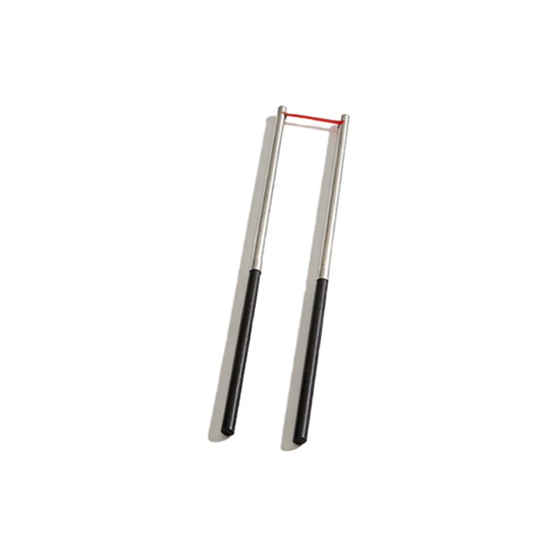
The most crucial step in adjusting a through-beam sensor is achieving precise mechanical alignment. Begin by mounting both units securely on stable brackets or fixtures. Power on the devices. Most through-beam receivers have a visual alignment indicator, such as a green LED that lights when the beam is correctly received. Loosen the mounting hardware slightly to allow for adjustment. Manually aim the transmitter at the receiver. Slowly adjust the angle and position of one unit until the receiver's "beam received" indicator activates steadily. For long-range applications, use a sighting tool if provided, or a laser pointer can be a helpful makeshift tool for initial rough alignment. Once the indicator is stable, carefully tighten the mounting hardware while observing the indicator to ensure alignment is not lost during tightening.
Utilizing Alignment Indicators and Sensitivity Adjustment
After basic mechanical alignment, fine-tune the setup using the sensor's built-in indicators. The receiver typically has a two-stage LED: a green LED for power/beam reception and a yellow or orange LED for output status. A stable green light confirms beam alignment. Some advanced models feature a bar-graph or digital signal strength display. Observe this indicator while making minute adjustments to maximize the signal strength. This step is vital for ensuring a strong margin against potential signal degradation. While pure through-beam sensors often have fixed sensitivity, some models include a potentiometer or teach-in function to adjust the detection threshold. This can be useful in environments with slight background light noise or to ignore small, non-target objects like dust particles.
Testing and Validating Sensor Performance
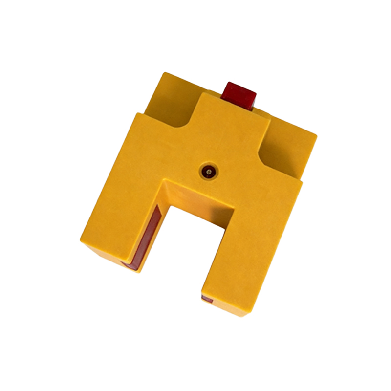
Do not assume the sensor is operational after alignment alone. Comprehensive testing under real or simulated conditions is mandatory. Introduce the target object at various points across the entire sensing window, especially at the edges. The sensor should consistently detect the object. Check for missed detections or chatter. Next, perform a "margin test" to ensure reliability. Gradually introduce a known interference, such as a gradual buildup of translucent dust on the lenses or a slight misalignment, and verify the sensor continues to operate correctly until a defined limit. This establishes a safety margin. Test the sensor's response time with a fast-moving target to ensure it meets the application's cycle time requirements without false triggers.
Troubleshooting Common Alignment Issues
If the receiver's indicator is unstable or fails to light, begin systematic troubleshooting. First, double-check all electrical connections and power supply. Confirm that the transmitter is emitting light; some have a visible red beam or a test point. Ensure the lens surfaces on both units are clean and free of obstructions. Verify that the object is fully interrupting the beam; for small objects, the beam diameter might be too large. In environments with strong ambient light, shield the receiver from direct exposure or use a sensor with a modulated light source and synchronous detection. For long-range setups, atmospheric conditions like heat haze can bend the beam; consider using a laser-based sensor for a more collimated beam. Persistent issues may require realigning from scratch or checking for mechanical flex or vibration.
Implementing Best Practices for Long-Term Stability
Once optimally adjusted, take steps to maintain sensor performance. Use sturdy, vibration-resistant mounting hardware. Install physical guards or barriers to protect the sensors from accidental impact or debris. Establish a regular maintenance schedule to clean the lenses with appropriate materials. Periodically re-check the alignment and signal strength as part of preventative maintenance, especially if the machinery is subject to vibration or thermal cycling. Document the alignment settings and signal strength values for future reference. For critical applications, consider installing a monitoring system that alerts personnel if the received signal strength falls below a safe threshold, enabling proactive maintenance before a failure occurs.