Understanding Proximity Sensor Basics
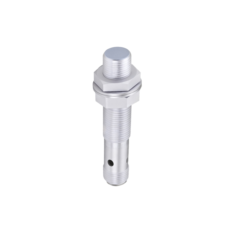
Proximity sensors are vital components in industrial automation, detecting the presence or absence of an object without physical contact. They primarily operate on inductive, capacitive, or photoelectric principles. Inductive sensors detect metallic objects, capacitive sensors can detect both metallic and non-metallic materials, and photoelectric sensors use light beams. Before wiring, it is crucial to identify the sensor type (e.g., NPN or PNP output, normally open or normally closed) and its specifications, such as operating voltage and current ratings, as stated on the sensor's datasheet or nameplate. This foundational knowledge ensures compatibility with your control system, typically a Programmable Logic Controller (PLC) or relay.
Essential Tools and Safety Precautions
Gather the necessary tools before starting: appropriate screwdrivers, wire strippers, crimping tools, ferrules for stranded wires, and a multimeter for verification. Safety is paramount. Always disconnect and lock out all power sources to the control circuit. Verify that the voltage is off using the multimeter. Wear appropriate personal protective equipment (PPE). Ensure the sensor's housing integrity is not compromised, and confirm the environmental conditions (temperature, humidity, exposure to chemicals) are within the sensor's specified limits to prevent premature failure or hazardous situations.
Interpreting the Connection Diagram
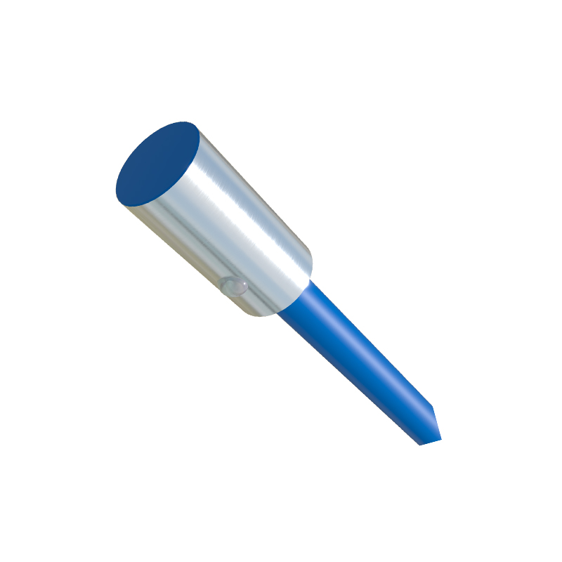
Every proximity sensor has a connection diagram, usually found on its body or in the accompanying documentation. Typically, a three-wire DC sensor will have wires or terminals labeled as follows: Brown wire for positive DC supply (+V, e.g., +24VDC), Blue wire for negative DC supply or common (0V, GND), and Black wire for the output signal. For a PNP sensor (sourcing), the black wire outputs positive voltage when activated. For an NPN sensor (sinking), the black wire connects to ground when activated. Some sensors may have additional wires for diagnostic functions or a separate shield wire. Understanding this color code and labeling is the key to correct wiring.
Wiring a 3-Wire DC PNP Proximity Sensor
A PNP sensor is commonly used with PLCs that have a sinking input module. Follow these steps: First, connect the sensor's blue wire to the DC power supply's negative terminal (0V). Second, connect the sensor's brown wire to the DC power supply's positive terminal (+24V). Third, connect the sensor's black (output) wire to the input channel of your PLC or relay. Finally, connect the common terminal of the PLC input module back to the DC power supply's negative terminal (0V), completing the circuit. When a target is detected, the PNP sensor will source positive current from the black wire into the PLC input, signaling a "TRUE" or "ON" state.
Wiring a 3-Wire DC NPN Proximity Sensor
An NPN sensor is typically used with PLCs that have a sourcing input module. The wiring sequence is similar but with a critical difference in the current path. First, connect the sensor's brown wire to the DC power supply's positive terminal (+24V). Second, connect the sensor's blue wire to the DC power supply's negative terminal (0V). Third, connect the sensor's black (output) wire to the input channel of your PLC. Finally, connect the common terminal of the PLC input module to the DC power supply's positive terminal (+24V). When activated, the NPN sensor sinks current, allowing current to flow from the PLC input common, through the input circuit, and out through the black wire to ground (0V).
Connecting to a PLC Digital Input Module
Integration with a PLC requires matching the sensor's output type with the input module's circuitry. For a sinking input module (common connected to +V), you must use a PNP sensor. For a sourcing input module (common connected to 0V), you must use an NPN sensor. Mismatching these can lead to incorrect operation or damage. Always use shielded cable for the sensor wiring, especially in electrically noisy environments. Connect the cable shield to a functional earth ground at the control panel end only, avoiding ground loops. This practice minimizes electromagnetic interference (EMI) on the signal.
Testing and Troubleshooting the Installation
After wiring, apply power cautiously. Use a multimeter to check voltages. Measure between the brown and blue wires to confirm the supply voltage (e.g., 24V DC). To test sensor operation, place the target object within the sensor's sensing range. For a PNP sensor, the voltage between the black and blue