Understanding the Fundamentals of Proximity Sensing
Proximity sensors, including inductive, capacitive, and photoelectric types, are fundamental components in industrial automation. They operate by generating an electromagnetic field, an electrostatic field, or a beam of light to detect the presence or absence of a target object without physical contact. The reliability of these sensors is paramount for process control, safety systems, and machinery sequencing. However, their operational principles inherently make them susceptible to various forms of external influence. The core question is not if interference can occur, but under what conditions it manifests and how it can be effectively mitigated. A deep understanding of the sensor's technology is the first step in diagnosing and preventing disruptive issues.
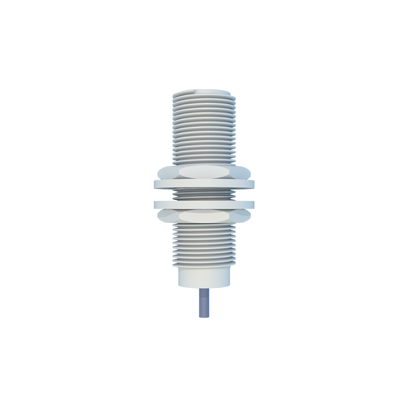
Common Sources of Electrical and Environmental Interference
Interference for proximity sensors typically stems from electromagnetic, electrostatic, or optical sources. Electromagnetic interference (EMI) is a primary concern, especially for inductive sensors. Sources include nearby high-current AC cables, variable frequency drives (VFDs), welding equipment, and large motors. These can induce spurious voltages in the sensor or its cabling, causing false triggering or failure to detect. For capacitive sensors, changes in environmental humidity, the presence of dust, or non-target materials can alter the dielectric constant, leading to erratic behavior. Photoelectric sensors face optical interference from ambient light (sunlight, strobe lights) or reflective surfaces that bounce the beam unexpectedly. Even physical factors like vibration, which can change the relative position of the sensor, or extreme temperatures affecting electronic components, are forms of environmental interference.
Specific Interference Scenarios in Industrial Settings
In a real-world panel or machine, several specific scenarios are common. Sensor mutual interference occurs when two or more inductive sensors are mounted too closely together. Their oscillating magnetic fields can couple, causing one sensor to lock on or destabilize. Another frequent issue is ground loop interference, where differences in electrical potential between the sensor ground and the controller ground cause current to flow through the signal cable, corrupting the output signal. Noise on the DC power supply line, often from shared loads like solenoids or contactors, can also be superimposed on the sensor's operating voltage. For photoelectric sensors, cross-talk between units operating at similar frequencies or with overlapping beams in a confined space is a typical problem.
Diagnosing Interference Issues: A Methodical Approach
When a proximity sensor behaves erratically, a systematic diagnostic approach is essential. Begin by verifying the mechanical installation: check mounting stability, sensing distance, and target alignment. Next, examine the electrical installation. Inspect cable routing; ensure sensor cables are not run in parallel with high-power cables. If they must cross, they should do so at a 90-degree angle. Use shielded cables and verify that the shield is properly grounded at only one end, typically the controller side. Temporarily powering the sensor from an isolated, clean power supply can help determine if noise is coming from the main supply line. Monitoring the sensor output with an oscilloscope can reveal noise patterns indicative of specific interference types, such as high-frequency switching noise from VFDs.
Effective Mitigation Strategies and Best Practices
Preventing interference is more effective than curing it. Key strategies include proper sensor selection. Choose a sensor with a robust housing rating (IP67 or higher) for harsh environments and consider models with built-in noise immunity features. Correct installation is critical: maintain adequate separation distances between sensors and between sensor cables and power lines. Always use the manufacturer-recommended cable type, preferably twisted-pair and shielded. Implement proper grounding by creating a single-point star ground system for the control panel to avoid ground loops. For AC sensors, installing a snubber circuit across the load can suppress voltage spikes. For DC systems, ferrite cores clamped onto the cable near the sensor or controller can absorb high-frequency noise. For photoelectric sensors, use models with modulated light and select a frequency less susceptible to ambient light fluctuations.
Advanced Solutions and Concluding Recommendations
For persistently challenging environments, advanced solutions may be necessary. Fiber optic photoelectric sensors are highly immune to EMI and are ideal for areas with extreme electrical noise. Some modern sensors feature advanced diagnostics via IO-Link, which can provide data on signal strength, temperature, and operating voltage, aiding in pre-failure detection of interference-related stress. In conclusion, while proximity sensors are susceptible to interference, a combination of informed sensor selection, meticulous installation practices, and adherence to proven noise reduction techniques will ensure robust and reliable operation. The engineer's role is to anticipate these challenges during the design phase and implement a defense-in-depth strategy against all forms of electrical and environmental interference.