Understanding Proximity Switch Sensor Components
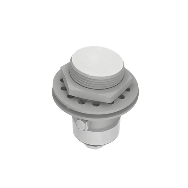
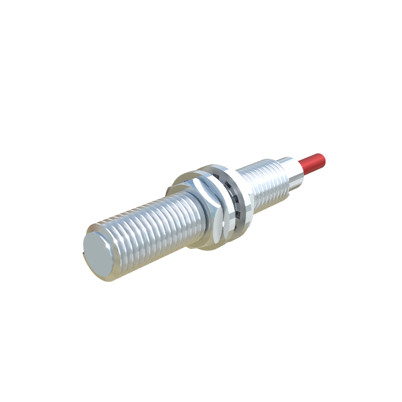
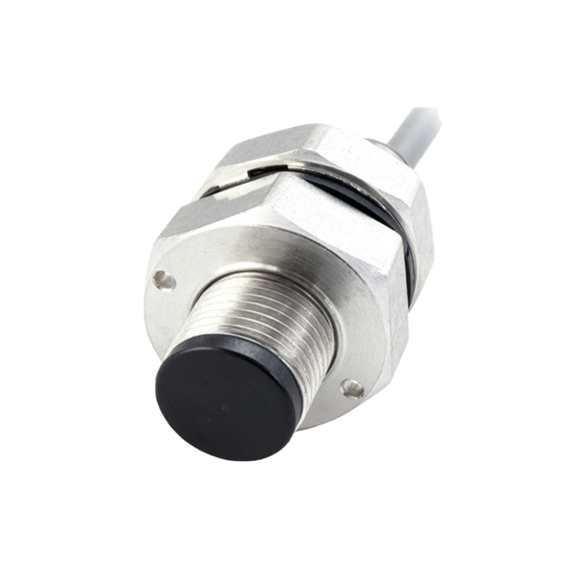
Before attempting to remove the wires from a proximity switch sensor, it is crucial to understand its basic components. A typical inductive or capacitive proximity sensor consists of a sensing face, a housing, and an electrical connection point, usually a pre-wired cable or a connector plug with multiple wires. These wires are typically color-coded: brown for positive DC supply (+V), blue for negative DC supply (0V), and black for the switched output signal. Some models may have additional wires for complementary outputs or diagnostic functions. Identifying these wires and their corresponding terminals is the first step in the removal process. Always refer to the manufacturer's datasheet or wiring diagram specific to your sensor model, as color codes can vary, especially with AC sensors or sensors from different regions.
Essential Safety Precautions and Preparations
Safety is the paramount concern when working with industrial electrical components. Begin by following proper lockout/tagout (LOTO) procedures to isolate the electrical circuit controlling the sensor. Verify that the power is completely disconnected using a multimeter. Ensure the machine or system is in a safe state and cannot be accidentally energized. Gather the necessary tools, which typically include appropriate screwdrivers (flat-head or Phillips, often smaller sizes), a set of precision pliers, wire cutters/strippers if needed, and possibly a connector extraction tool. Wearing personal protective equipment (PPE) like safety glasses and insulated gloves is a recommended practice. Clear the work area and ensure you have adequate lighting to see the small terminals and wire connections clearly.
Step-by-Step Wire Removal from Connector-Based Sensors
Many modern proximity sensors utilize quick-disconnect connectors (e.g., M8, M12 types). For these, the process is straightforward. First, grasp the connector body firmly. If it is a threaded coupling type, unscrew it by turning it counterclockwise. For push-pull connectors, depress any locking tab or collar while pulling the connector straight out from the sensor body. Do not pull on the wires themselves. Once the connector is detached from the sensor, you can proceed to disconnect the individual wires from the other end of the cable, which is typically connected to a junction box or PLC I/O module. At that terminal point, use a screwdriver to loosen the terminal screw, gently pull the wire out, and identify it with a label if necessary for future reinstallation.
Step-by-Step Wire Removal from Pre-Wired or Integral Cable Sensors
Sensors with a fixed, pre-wired integral cable require a different approach. These wires are connected directly to internal terminals inside the sensor housing. Start by loosening and removing the sensor from its mounting bracket. Carefully unscrew or unclip the sensor's rear housing or cable gland. Inside, you will find the terminal block or PCB where the wires are secured. Note the exact position of each wire. Using a small screwdriver, loosen the terminal screw for each wire just enough to release the conductor. Avoid over-loosening. Gently pull the wire straight out from the terminal. If the cable is held by a strain relief gland inside the housing, you may need to loosen that as well to free the entire cable assembly. Handle the wires delicately to avoid breaking the fragile strands.
Dealing with Challenges and Common Issues
During removal, you may encounter several common issues. Corroded or seized terminal screws can be problematic. Apply a small amount of electrical contact cleaner or penetrating oil and allow it to sit before carefully attempting to loosen the screw. If wires are stuck due to melted insulation or environmental sealing compounds, use precision cutters to trim away a minimal amount of material. For sensors in tight spaces, consider using flexible shaft or right-angle screwdrivers. Never apply excessive force, as this can damage the sensor's internal electronics or break the terminal block. If a wire breaks off inside the terminal, you may need to use fine tweezers or a specialized extraction tool to remove the fragment before inserting a new wire.
Post-Removal Inspection and Best Practices
After successfully removing the wires, conduct a thorough inspection. Check the condition of the wire strands for corrosion, nicks, or breaks. Inspect the insulation for cracks, brittleness, or heat damage. Examine the sensor's terminals for signs of arcing, discoloration, or physical damage. This is an ideal time to test the sensor's functionality with a multimeter if possible, before reinstalling or replacing it. For future maintenance, always label wires immediately after removal. When installing a new sensor or reconnecting wires, ensure they are routed neatly, away from moving parts or heat sources, and properly secured with strain relief. Following