Introduction to Slot Type Photoelectric Sensors
Slot type photoelectric sensors, also known as through-beam sensors, consist of an emitter and a receiver housed in a single U-shaped body. The emitter projects a light beam across the slot to the receiver. When an object passes through the slot, it interrupts this beam, causing the sensor to change its output state. These sensors are widely used in industrial automation for applications such as object detection, counting, and position verification due to their high precision and reliability. Their compact, integrated design makes them easier to install and align compared to separate emitter-receiver pairs.
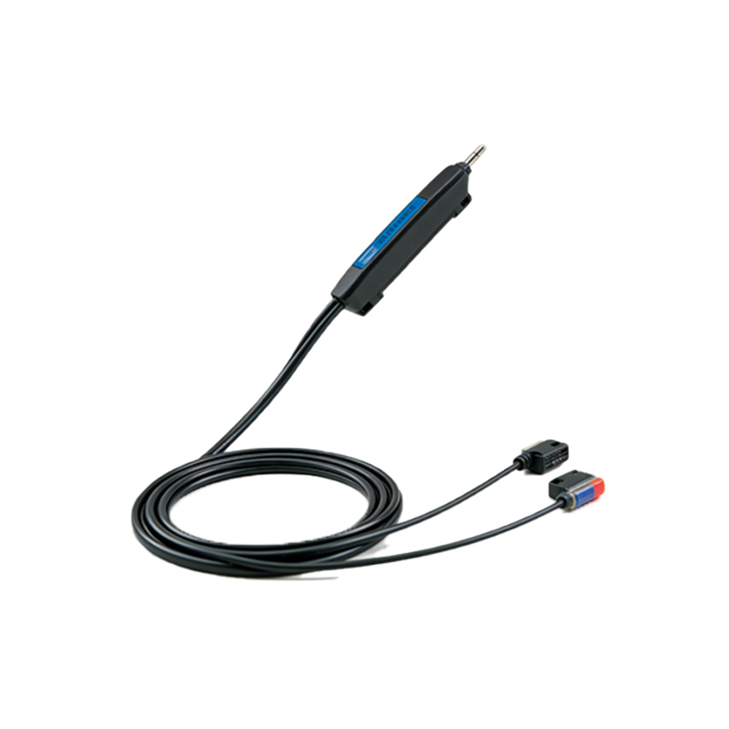
Fundamentals of Two-Wire Connection
The two-wire connection is one of the simplest wiring configurations for sensors. In this setup, the sensor has only two terminals for connection: one for power (typically labeled as brown wire or +) and one for the output signal (typically labeled as blue wire or -). The sensor operates by drawing a small leakage current even when in the "off" state. When the sensor is activated (e.g., the light beam is interrupted), it allows a larger current to flow, which can drive a load such as a PLC input, relay, or indicator light. This configuration is cost-effective and reduces wiring complexity, but it requires careful consideration of voltage drop and load compatibility.
Detailed Two-Wire Wiring Diagram
A standard wiring diagram for a two-wire slot type photoelectric sensor involves connecting it in series with the power supply and the load. Connect the brown wire (positive/power) from the sensor to the positive terminal of the DC power supply (commonly 10-30 VDC). Connect the blue wire (negative/output) from the sensor to one terminal of the load (e.g., a PLC digital input module). The other terminal of the load is then connected back to the negative terminal of the power supply. This forms a complete circuit. Ensure the power supply voltage matches the sensor's rated voltage, and verify that the load current does not exceed the sensor's maximum switching capacity to prevent malfunction or damage.
Key Considerations for Installation
Proper installation is crucial for reliable operation. First, ensure the sensor is securely mounted with the slot aligned perpendicular to the object's path. Avoid mounting in areas with excessive vibration or ambient light interference, as this can cause false triggering. For the electrical connection, use shielded cables in environments with high electromagnetic interference (EMI) and keep cable lengths as short as possible to minimize voltage drop. Always follow the manufacturer's specifications for wire gauge and torque settings on terminal screws. Additionally, consider using a protective circuit or fuse to safeguard against short circuits or overcurrent conditions.
Common Applications and Troubleshooting
Slot type photoelectric sensors with two-wire connections are commonly employed in conveyor systems for detecting package presence, in assembly lines for part counting, and in security systems for door monitoring. If the sensor fails to operate, start by checking the power supply voltage with a multimeter to ensure it is within range. Verify all wiring connections are tight and correct according to the diagram. Inspect the sensor slot for dirt or obstructions that might block the light beam. If the load does not activate, test the sensor by temporarily connecting a known working load (like an LED) to isolate the issue. Consult the sensor's datasheet for specific diagnostic indicators or error codes.
Advantages and Limitations
The two-wire configuration offers significant advantages, including simplified wiring, lower installation costs, and space savings in control panels. It is ideal for applications with limited space or where many sensors are used. However, limitations include potential voltage drop across the sensor, which can affect performance in long cable runs, and the need for the load to have a suitable input impedance. Some PLC inputs may require additional resistors to work correctly with two-wire sensors. Always evaluate the specific application requirements against these factors to ensure optimal sensor selection and performance.