Understanding M5 Proximity Sensor Fundamentals
M5 proximity sensors represent a category of high-precision, non-contact sensing devices widely utilized in industrial automation and control systems. These sensors operate on the principle of electromagnetic induction or capacitive coupling, depending on the specific model (inductive or capacitive). Their primary function is to detect the presence or absence of a metallic or non-metallic target object within a defined sensing range without physical contact. The "M5" designation often refers to a compact, cylindrical form factor with an 5mm diameter threaded barrel, making them ideal for space-constrained installations. Key internal components typically include an oscillator, a sensing coil, a signal amplifier, and an output switching circuit. Understanding this foundational operation is crucial for correct application, as it dictates the sensor's suitability for detecting different materials—inductive types for metals and capacitive types for a broader range including liquids and plastics.
Selecting the Right M5 Sensor for Your Application
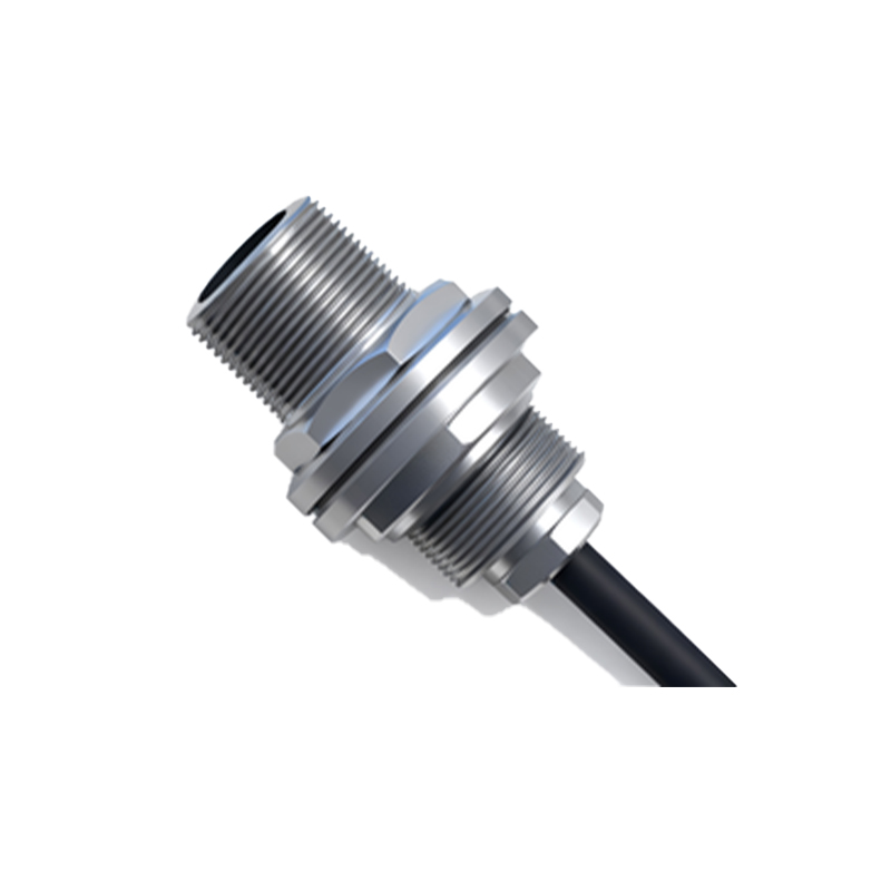
Proper selection is the first critical step toward effective usage. Begin by defining the application parameters: target material (ferrous metal, non-ferrous metal, plastic, liquid), required sensing distance (the rated operating distance, typically a few millimeters for M5 sizes), environmental conditions (temperature, humidity, presence of dust or chemicals), and required output type (NPN/PNP transistor, NO/NC contact). For metallic targets in clean industrial environments, shielded inductive M5 sensors are common, offering flush-mounting capability. For non-metallic targets or applications requiring detection through a container wall, a capacitive M5 sensor is necessary. Always consult the manufacturer's datasheet to verify the exact sensing characteristics, temperature ratings, and electrical specifications like supply voltage (commonly 10-30V DC) and current consumption to ensure compatibility with your control system.
Correct Installation and Mounting Procedures
Installation accuracy directly impacts sensor performance and longevity. For threaded M5 sensors, ensure the mounting hole is precisely machined to prevent housing stress. Maintain the recommended clearance around the sensor's active face; for unshielded (non-flush) inductive sensors, a metallic-free zone is mandatory to prevent false triggering. The sensing face must be positioned parallel to the target's approach direction for optimal detection. Secure wiring is paramount: use the specified cable type or pre-wired models, and connect the leads correctly—brown wire to positive DC, blue wire to negative DC, and black (or white) wire as the switched output to your PLC or controller input. Employ conduit or cable carriers in high-vibration environments to prevent wire fatigue. Always power down the circuit during installation to avoid electrical shorts or sensor damage.
Wiring and Electrical Integration
Electrical integration involves connecting the sensor to a power source and the load (e.g., PLC input, relay, indicator). For a standard 3-wire DC sensor, the wiring configuration is straightforward. For an NPN sinking output sensor (common in many regions), the black output wire switches the negative side; the load is connected between the positive supply and the sensor's output. For a PNP sourcing output, the output switches the positive side. It is critical to include a protective fuse in the supply line and, if necessary, a surge suppressor for inductive loads like relays. Ensure the controller's input impedance matches the sensor's residual current specification when off. For applications in noisy electrical environments, use shielded cables and ground the shield at one end to the control panel's earth ground to minimize electromagnetic interference (EMI).
Configuration, Testing, and Calibration
Most standard M5 proximity sensors are pre-calibrated at the factory and do not feature user-adjustable sensing distance. However, fine-tuning involves ensuring the target enters the effective operating range reliably. Use the manufacturer's specified test target (usually a square of mild steel for inductive sensors) for verification. The real sensing distance can be affected by the target material's size, shape, and composition. For capacitive sensors, a sensitivity potentiometer is often provided. Adjust this potentiometer with the target in place until the output reliably switches, then back off slightly to avoid detecting background objects. Always test under actual operating conditions, including temperature extremes and with the intended target moving at the operational speed, to verify consistent detection without false pulses.
Troubleshooting Common Operational Issues
Systematic troubleshooting resolves most field issues. If the sensor fails to detect, first verify power supply voltage at the sensor terminals under load. Check for loose connections, damaged cables, or incorrect wiring polarity. Use a multimeter to monitor the output state relative to the supply common. If output is erratic, investigate potential interference from nearby motors, frequency drives, or other sensors operating at