Introduction to Fiber Optic Proximity Sensing
Fiber optic proximity switches represent a sophisticated category of non-contact sensors that utilize light transmission through flexible fiber optic cables to detect the presence or absence of objects. Unlike traditional inductive or capacitive proximity sensors, the core sensing element—the optical pair (transmitter and receiver)—is located remotely in an amplifier unit. The sensing function is performed at the tip of the fiber optic cable, which guides light to and from the target. This fundamental architecture grants these sensors unique advantages, making them indispensable in challenging industrial environments characterized by extreme temperatures, intense electromagnetic interference (EMI), corrosive atmospheres, or highly confined spaces where conventional electronic sensors cannot physically fit or survive.
Core Operating Principles and Sensing Modes
Fiber optic proximity sensors operate primarily in two distinct modes: through-beam and diffuse reflective. In the through-beam mode, also known as the opposed mode, the transmitter and receiver fibers are housed in separate cables facing each other. Detection occurs when an object interrupts the light beam traveling from the transmitter to the receiver. This mode offers the longest sensing ranges and highest accuracy. The diffuse reflective mode, or proximity mode, integrates both transmitting and receiving fibers into a single cable. The sensor detects an object when light emitted from the transmitter fiber reflects off the target's surface and is captured by the adjacent receiver fiber. The effective sensing distance in this mode depends heavily on the target's color, material, and surface finish, with lighter, more reflective surfaces providing longer ranges.
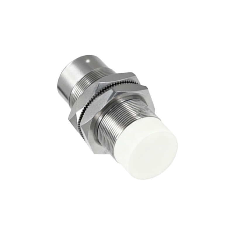
Key Components: Fibers, Amplifiers, and Tips
The performance of a fiber optic sensor system hinges on its three main components. First, the fiber optic cable itself, typically made from glass or plastic fibers. Glass fibers offer superior temperature resistance and transmission efficiency for long distances, while plastic fibers are more cost-effective, flexible, and resistant to breakage for shorter runs. Second, the amplifier or controller unit houses the light source (often an LED) and photodetector, processes the signal, and provides the output (e.g., NPN/PNP, analog). Modern amplifiers feature teach-in functions, adjustable sensitivity, and timers. Third, the lens or tip at the sensing end shapes the light beam. Different tip configurations—such as focused, convergent, or coaxial—create varied spot sizes and sensing fields, allowing optimization for detecting tiny objects, ignoring background, or providing a precise cutoff point.
Advantages Over Conventional Proximity Sensors
The inherent design of fiber optic sensors confers several compelling benefits. Their immunity to EMI and radio frequency interference (RFI) is paramount in applications near welders, motors, or variable frequency drives. The sensing head contains no electronics, enabling reliable operation in ovens, freezeers, or washdown areas with wide temperature ranges from -40°C to over 200°C. The small size of the fiber tip allows detection of minute components in electronics assembly or textile machinery. Furthermore, the flexibility and length of the cables (up to tens of meters) provide exceptional installation versatility, separating the sensitive amplifier from the harsh point of detection. They also pose no risk of sparking, making them suitable for potentially explosive atmospheres when paired with appropriate intrinsic safety barriers.
Primary Industrial Applications and Use Cases
These sensors find critical roles across diverse sectors. In semiconductor and electronics manufacturing, they verify the presence of tiny chips, leads, or connectors on circuit boards. Within packaging and bottling lines, they count, inspect, and monitor labels, caps, and fill levels, often at high speeds. Automotive manufacturers employ them for robot guidance, part positioning in welding cells, and checking for part presence in aggressive painting environments. In metalworking, they detect the edge of thin materials like foil or the teeth on a spinning saw blade. Medical device production leverages their cleanliness and precision for assembly verification. Their ability to function in vacuum chambers also makes them vital in specialized processes like chemical vapor deposition.
Critical Selection Criteria and Installation Tips
Selecting the right fiber optic sensor requires careful analysis. Begin by defining the target material, size, color, and required sensing distance. For small, dark targets at a distance, a through-beam system is preferable. For detecting variations in color or surface finish, a high-resolution diffuse sensor with adjustable sensitivity is necessary. Consider the environmental conditions: temperature dictates the choice between glass and plastic fibers; exposure to chemicals or abrasion may require fibers with specific jacketing like PTFE or stainless steel armor. During installation, ensure fibers are not bent beyond their minimum bend radius to prevent light loss or cable damage. Properly align through-beam pairs and shield the sensing area from ambient light contamination, such as from overhead lamps or sunlight, which can cause false triggering