Understanding Proximity Sensor Sensitivity
Proximity switch sensors are fundamental components in industrial automation, relying on electromagnetic fields, capacitance, or ultrasonic waves to detect the presence or absence of an object without physical contact. When a sensor is deemed "insensitive," it typically means its detection range has decreased, it fails to detect targets reliably, or it exhibits inconsistent switching behavior. This lack of sensitivity directly impacts production line efficiency, can cause machine stoppages, and may lead to defective products. The first step in troubleshooting is to confirm the symptom: is the sensor not detecting at the expected distance, or is it intermittently failing? Precise diagnosis is crucial before implementing any corrective action.
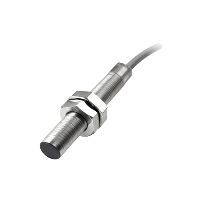
Primary Causes of Reduced Sensitivity
Several factors can degrade a proximity sensor's performance. Environmental contamination is a leading cause. Accumulation of metallic dust, chips, oil, or coolant on the sensor's active face can dampen or distort its sensing field. For inductive sensors, the presence of ferrous debris is particularly problematic. Electrical interference from nearby high-voltage cables, frequency drives, or welding equipment can induce noise, disrupting the sensor's signal processing. Mechanical issues, such as sensor misalignment or loosening of its mounting, can alter the effective gap between the sensor and the target. Finally, the sensor itself may be failing due to internal component aging, damaged cabling, or exposure to extreme temperatures beyond its specified rating.
Step-by-Step Troubleshooting Procedure
Begin with a visual and physical inspection. Power down the equipment, lock out/tag out, and clean the sensor's sensing face thoroughly with a non-abrasive cloth and appropriate solvent. Check for any physical damage to the housing or cable. Verify the sensor is securely mounted and correctly aligned perpendicular to the target's approach path. Next, examine the electrical installation. Ensure the power supply voltage is within the sensor's specified range, as undervoltage can cause weak operation. Inspect the wiring for loose connections, fraying, or poor terminations. Check that the load (e.g., PLC input, relay) is within the sensor's switching capacity. Use a shielded cable if not already installed, and ensure the shield is properly grounded at the control panel end only.
Optimizing Installation and Setup
Correct installation is paramount for optimal sensitivity. Always refer to the sensor's datasheet for its rated sensing distance (Sn). For standard applications, the operational mounting distance should be set at 70-80% of Sn to account for target variations and temperature drift. Ensure the target object meets the sensor's specifications regarding material, size, and approach speed. For inductive sensors, note that different metals have correction factors; stainless steel, for example, reduces the effective sensing range. Increase the target size if possible. For capacitive sensors, adjust the sensitivity potentiometer to avoid false triggers from background materials while ensuring it is sensitive enough to the target. Minimize the distance between the sensor and the controller to reduce voltage drop and signal attenuation.
Addressing Electrical Noise and Interference
Electrical noise is a common culprit for erratic sensitivity. Implement robust noise suppression measures. Install ferrite cores on the sensor cable near the connector. Use twisted-pair and shielded cables, ensuring the shield is grounded at the control cabinet, not at the sensor end. Physically separate sensor cables from power lines, motor leads, and other high-noise sources by at least 20-30 cm. If using DC sensors, connect a bypass capacitor (e.g., 0.1-1 µF) across the load terminals close to the sensor to absorb voltage spikes. For sensors in high-noise environments, consider models with built-in noise immunity features or a higher IP rating for protection against contaminants that might also conduct interference.
When to Adjust, Repair, or Replace
If basic cleaning and verification do not restore sensitivity, consult the sensor's manual for a sensitivity adjustment potentiometer. Make small, incremental adjustments while testing with the target. If the sensor has a teach-in function, recalibrate it according to the procedure. If problems persist, perform a substitution test with a known-good sensor of the same model. This quickly isolates whether the issue is with the sensor unit or the external circuit/environment. For older sensors, consider that the oscillator components may have drifted with age. Continuous operation in harsh conditions can lead to internal moisture ingress or component failure. In such cases, repair is often not cost-effective, and replacement with a newer, more robust model is the recommended long-term solution.
Selecting a More Suitable Sensor
Persistent sensitivity issues may indicate the initial sensor selection was incorrect for the application. Re-evaluate the operating environment and requirements. For detecting small or non-fer