Understanding Proximity Sensor Fundamentals
Proximity sensors are indispensable components in modern industrial automation, providing non-contact detection of metallic or non-metallic objects. Their primary function is to sense the presence or absence of a target within a specified range without any physical contact, thereby eliminating mechanical wear and enabling high-speed operation. These sensors operate on various principles, including inductive, capacitive, ultrasonic, and photoelectric technologies. Inductive sensors, for instance, generate an electromagnetic field to detect metallic objects, while capacitive sensors can detect both metallic and non-metallic materials by measuring changes in capacitance. The reliability and longevity of these devices make them critical for applications ranging from assembly line part detection and machine safety to position verification and counting tasks. The choice between different wiring configurations—specifically two-wire and three-wire systems—is a fundamental engineering decision that impacts circuit design, installation, maintenance, and overall system performance.
The Two-Wire Proximity Sensor Configuration
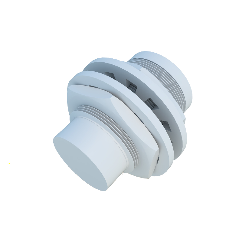
The two-wire proximity sensor is renowned for its simplicity and direct integration capabilities. As the name implies, this sensor requires only two wires for its entire operation: one for the power supply (L+) and the other for the load connection (L-). It is connected in series with the load, much like a conventional switch. This design makes it exceptionally easy to install and wire, often serving as a direct replacement for mechanical limit switches in existing control circuits. The primary advantage lies in its reduced wiring complexity and lower initial installation cost. However, this simplicity comes with certain trade-offs. Two-wire sensors typically exhibit a higher residual current or leakage current when in the "off" state. This current, though small, must be carefully considered as it can sometimes be sufficient to inadvertently activate highly sensitive loads like PLC input modules or small relays, leading to potential malfunction. Additionally, they may have slightly lower switching speeds and higher voltage drops compared to their three-wire counterparts.
The Three-Wire Proximity Sensor Configuration
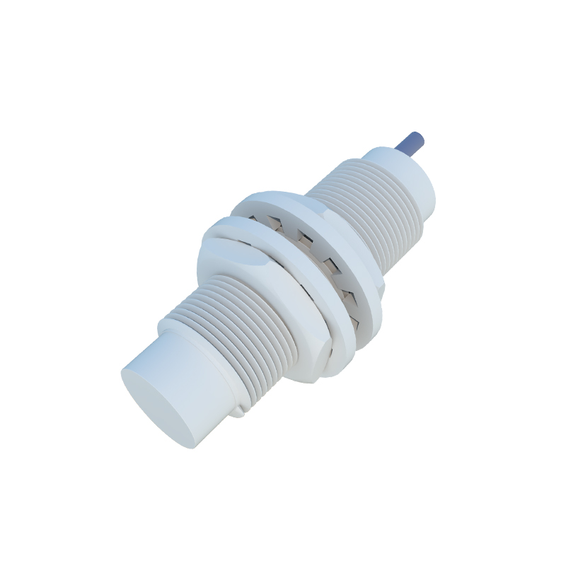
In contrast, the three-wire proximity sensor offers enhanced performance and greater control flexibility. This configuration separates the power supply and output signal paths, utilizing three distinct wires: a common wire (usually 0V or ground), a power supply wire (+V), and a separate output wire. The output can be either a sinking (NPN) or sourcing (PNP) transistor type, providing a clear, solid-state switch signal with minimal leakage current. The key benefit of this design is the virtually zero off-state current, eliminating the risk of accidental load activation. This makes three-wire sensors the preferred choice for interfacing directly with programmable logic controllers (PLCs), solid-state relays, and other sensitive electronic control units. They generally offer faster response times, higher switching frequencies, and better performance in electrically noisy environments due to the separated signal and power lines. The trade-off is the increased wiring complexity and the need for a dedicated common wire.
Key Comparative Factors: Performance and Application
Selecting between two-wire and three-wire sensors hinges on a detailed analysis of the application requirements. For basic on/off control in AC-powered circuits with robust loads like contactors or motor starters, the two-wire sensor is often perfectly adequate and cost-effective. Its simple series connection is ideal for high-voltage AC applications. Conversely, for DC circuits, high-speed counting, precise positioning, or when connecting to modern PLCs and digital inputs, the three-wire sensor is almost always mandatory. Its clean switching signal ensures reliable data acquisition. Other critical factors include the available power supply (AC vs. DC), the electrical characteristics of the load (minimum operating current, sensitivity), the required switching speed, and the environmental conditions such as electromagnetic interference. Engineers must also consider the total cost of ownership, which includes not just the sensor unit cost, but also wiring, troubleshooting time, and potential downtime due to misoperation.
Installation and Wiring Best Practices
Proper installation is crucial for optimal sensor performance and longevity. For two-wire sensors, it is essential to verify that the load's minimum operating current is below the sensor's specified residual current to ensure proper turn-off. A bleeding resistor may sometimes be required in parallel with the load to provide a minimum current path. For three-wire sensors, correct identification of the brown (L+), blue (L- or 0V), and black (output) wires is standard, though colors can vary by manufacturer and region. Always consult the datasheet. Shielding and proper grounding are highly recommended, especially for three-wire sensors in long cable runs or noisy environments to prevent false triggering. Both types should be mounted securely, with adequate clearance from metal surfaces (for inductive types) as specified by the manufacturer to ensure the correct sensing range