Introduction to Sensing Technologies
In the realm of industrial automation and machinery control, the accurate detection of motion and position is paramount. Two fundamental components that serve this critical function are speed sensors and proximity switches. While their names might suggest overlapping purposes, they are engineered for distinct applications and operate on different principles. Speed sensors are primarily designed to measure the rotational velocity or linear speed of a target, providing continuous data for process control and monitoring. Proximity switches, on the other hand, are non-contact devices used to detect the presence or absence of a metallic object within a specific range, acting as a digital on/off signal. Understanding their operational characteristics, advantages, and limitations is essential for selecting the right component for a given industrial task.
Operating Principles of Speed Sensors
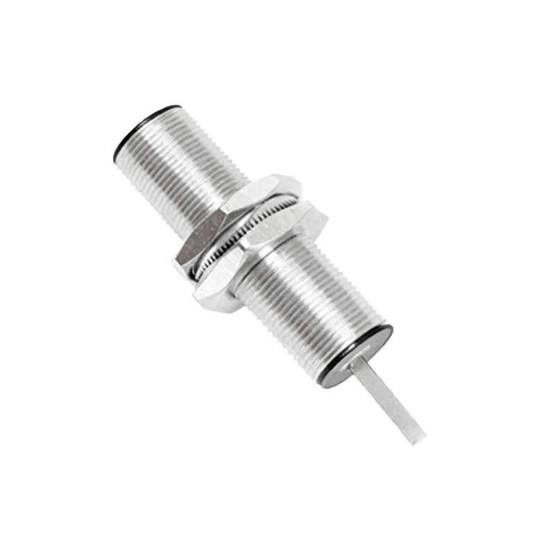
Speed sensors, often referred to as tachometers or RPM sensors, function by generating a signal proportional to the speed of a rotating shaft or moving object. Common types include magnetic inductive (variable reluctance) sensors, Hall-effect sensors, and optical encoders. A magnetic inductive sensor typically consists of a permanent magnet and a coil. When a ferrous target, such as a gear tooth, passes the sensor face, it disrupts the magnetic field, inducing a voltage pulse in the coil. The frequency of these pulses is directly proportional to the rotational speed. Hall-effect sensors utilize a semiconductor element that produces a voltage when exposed to a magnetic field from a rotating magnet or ferrous target. Optical encoders use a light source and a photodetector interrupted by a coded disk to generate precise digital pulses. These sensors output analog voltage, current (4-20 mA), or digital frequency signals, enabling integration with PLCs (Programmable Logic Controllers) and drive systems for real-time speed regulation and overspeed protection.
Operating Principles of Proximity Switches
Proximity switches are non-contact sensors that detect the presence of metallic objects without any physical contact. The most prevalent types are inductive proximity sensors and capacitive proximity sensors. Inductive proximity switches generate an oscillating electromagnetic field from a coil in their sensing face. When a conductive metal object enters this field, eddy currents are induced in the object, which dampens the oscillation. This change is detected by the sensor's circuitry, triggering a solid-state switch to change state (typically from open to closed). They are ideal for detecting ferrous and non-ferrous metals like steel, aluminum, and copper. Capacitive proximity switches can detect both metallic and non-metallic materials (plastics, wood, liquids) by sensing changes in capacitance caused by the target object entering an electrostatic field. Both types provide a discrete, binary output (PNP/NPN) used for tasks such as part counting, position verification, and end-of-travel limit switching.
Key Application Areas and Selection Criteria
The application dictates the choice between a speed sensor and a proximity switch. Speed sensors are indispensable in systems requiring continuous monitoring and control of velocity. Key applications include conveyor belt speed monitoring, motor and pump RPM measurement, turbine supervision, and automotive anti-lock braking systems (ABS). They provide the feedback necessary for closed-loop control, ensuring consistent process speed and preventing machinery damage from overspeed conditions. Proximity switches excel in discrete detection applications. They are widely used for object detection on assembly lines, determining the position of a machine component (like a cylinder rod), jam detection in material handling, and as safety interlocks on machine guards. Selection criteria involve the target material, required sensing distance (range), output signal type (analog vs. discrete), environmental conditions (temperature, presence of contaminants), and required response speed.
Installation and Environmental Considerations
Proper installation is critical for reliable operation. For speed sensors, especially magnetic types, the air gap between the sensor tip and the target (e.g., gear tooth) is a crucial parameter and must be set according to manufacturer specifications. Misalignment can lead to weak or erratic signals. The target must be of appropriate size and material to generate a sufficient signal. For proximity switches, the sensing distance, or "snap distance," is specified for a standard target (usually mild steel). Different materials and target sizes affect this range. Both sensor types must be rated for the operating environment. Factors such as ambient temperature extremes, vibration, humidity, oil, coolant spray, and electromagnetic interference (EMI) can significantly impact performance. Choosing sensors with appropriate IP (Ingress Protection) ratings, such as IP67 for washdown environments, and robust housing materials like stainless steel or PBT plastic, is essential for long-term reliability.
Advantages, Limitations, and Integration
Speed sensors offer the advantage of providing precise, real-time quantitative data essential for dynamic control systems. However