Laser position sensors are critical components in modern automation, manufacturing, and precision measurement systems. They provide non-contact, high-accuracy feedback for positioning, alignment, and inspection tasks. However, like any sophisticated electronic device, they are susceptible to faults that can disrupt entire production lines or measurement processes. Understanding the common causes, symptoms, and remedies for these faults is essential for maintaining operational efficiency and minimizing downtime.
One of the most prevalent issues is signal degradation or complete loss. This fault manifests as erratic readings, intermittent data, or a failure to detect a target. The root cause is often environmental contamination. Dust, oil mist, coolant, or other airborne particles can accumulate on the sensor's lens or the emitter/receiver windows, attenuating the laser beam. In harsh industrial environments, this is a constant battle. Regular, gentle cleaning of optical surfaces with appropriate materials, such as lens tissue and approved solvents, is the primary preventive measure. Furthermore, selecting sensors with adequate ingress protection (IP) ratings for the specific environment is crucial during the design phase.
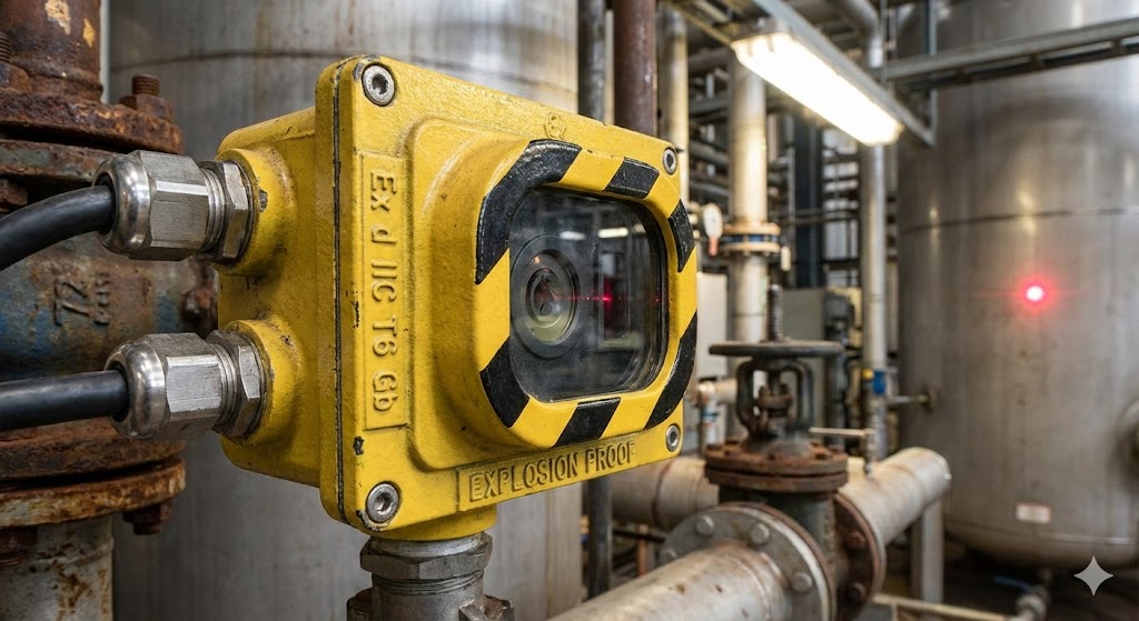
Another frequent culprit is incorrect installation or alignment. Laser sensors have specific requirements for mounting stability, sensing distance, and beam angle. Vibration can loosen mounts, causing the beam to drift off its intended target. Thermal expansion in machinery can also subtly shift alignment over time. Symptoms include consistent offset errors or failure to trigger at the expected position. Diagnosis involves verifying the mechanical mounting and using the sensor's alignment indicator (often an LED) or monitoring the real-time signal strength via software to precisely realign the beam to the target. Ensuring rigid mounts and considering thermal effects in the machine design can prevent this.

Electrical and interference problems are also common sources of fault. Power supply issues, such as voltage spikes, drops, or excessive noise, can damage internal components or cause unstable operation. Electromagnetic interference (EMI) from nearby motors, variable frequency drives (VFDs), or welding equipment can corrupt the sensitive analog or digital signals from the sensor. Symptoms range from random value jumps to complete lock-ups. Solutions include using stable, regulated power supplies, implementing proper grounding practices, employing shielded cables, and routing sensor cables away from high-power lines. In severe EMI environments, sensors with robust noise immunity or differential outputs should be selected.
The target surface itself can be a source of perceived sensor fault. Laser triangulation sensors, for instance, are highly sensitive to the color, reflectivity, and texture of the target. A shiny, specular surface can reflect the beam away from the receiver, while a dark, absorbent surface may not reflect enough light. Changing from a matte white to a glossy black part on a production line can cause a sensor to fail without any change in the sensor itself. Diagnosing this requires checking the target material against the sensor's specifications. Remedies include adjusting the sensor's sensitivity (if available), changing the installation angle to avoid direct reflection, or using a sensor type better suited to the application, such as a diffuse reflection model with background suppression or a confocal chromatic sensor for challenging surfaces.
Internal component failure is an inevitable possibility. The laser diode can degrade over time, losing output power. The receiver (PSD or CMOS chip) can be damaged by accidental exposure to excessive light, like direct sunlight or another laser. Electronic components can fail due to age, heat, or manufacturing defects. Diagnosis often involves process of elimination: if the environment is clean, alignment is perfect, electrical conditions are stable, and the target is ideal, yet the sensor performs poorly, internal failure is likely. Contacting the manufacturer's technical support for advanced diagnostics or considering sensor replacement is the standard course of action.
Finally, configuration and software errors can mimic hardware faults. An incorrectly set teaching point, an inappropriate response time, or a wrongly selected output mode (NPN vs. PNP, analog scaling) will lead to system malfunctions. Always double-check the parameter settings against the application requirements. Resetting to factory defaults and re-teaching the sensor under correct conditions can often resolve these "faults."
A systematic approach to troubleshooting is key. Start with the simplest checks: verify power and connections. Inspect the lens and target for cleanliness. Confirm the target is within the sensor's specified range and that its properties are suitable. Check alignment. Review environmental factors like new sources of contamination, vibration, or EMI. Examine configuration settings. By methodically eliminating these common external factors, maintenance personnel can accurately determine if a true internal sensor fault exists, enabling faster repairs and a quicker return to normal operation.