Understanding Through-Beam Photoelectric Sensors
Through-beam photoelectric sensors, also known as opposed-mode sensors, are fundamental components in industrial automation. They consist of two separate units: a transmitter and a receiver. The transmitter emits a constant beam of light, typically infrared or laser, which is detected by the receiver. An object is detected when it interrupts this light beam. This configuration offers the longest sensing range and highest reliability among photoelectric sensors, making it ideal for harsh environments with dust, dirt, or vibration. Before proceeding with any wiring, it is paramount to consult the specific datasheet provided by the sensor manufacturer. Specifications for voltage, current, wiring diagrams, and housing materials can vary significantly between models and brands.
Safety Precautions and Required Tools
Working with 220V AC power demands the utmost respect for safety protocols. Always ensure the main power supply is completely disconnected and locked out/tagged out (LOTO) before beginning any wiring work. Verify the absence of voltage using a properly rated multimeter. Wear appropriate personal protective equipment (PPE), including insulated gloves and safety glasses. The necessary tools typically include wire strippers, screwdrivers, a multimeter for verification, and possibly a DIN rail mounting clip. Use only wires with a gauge and insulation rating suitable for the expected current and the industrial environment. Proper grounding is not an option; it is an absolute necessity for safe operation.
Components and Terminal Identification
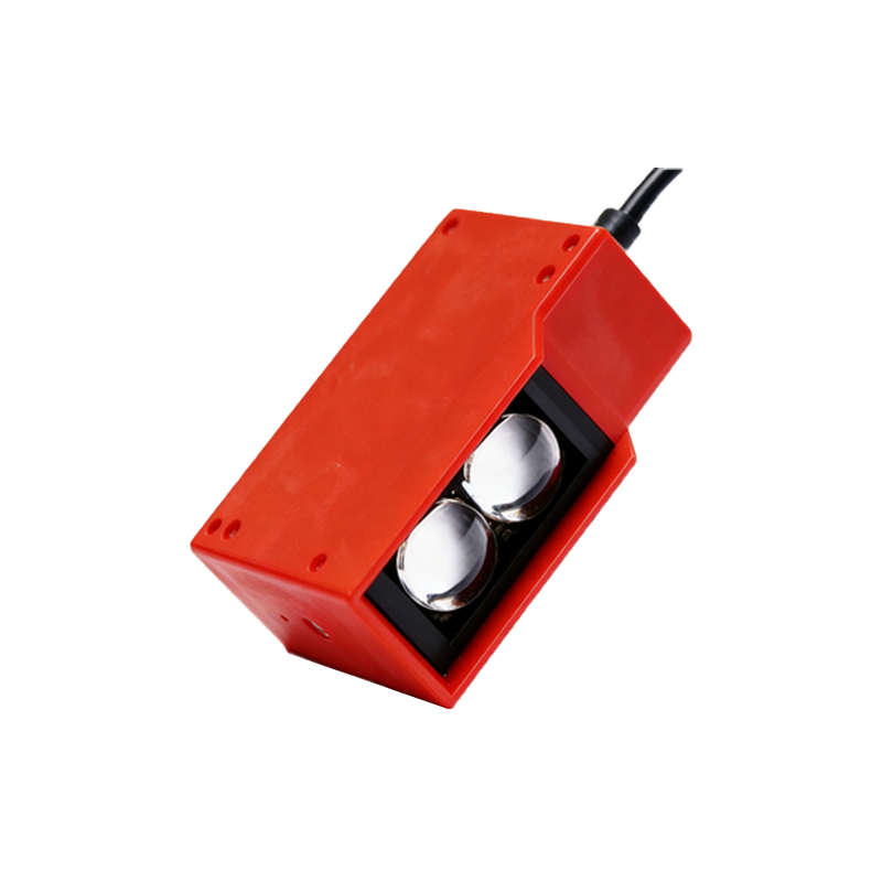
A standard through-beam sensor pair designed for 220V AC operation will have clearly marked terminals. The transmitter unit usually has only two terminals: Line (L) or Live (often brown wire) and Neutral (N) (often blue wire). Its sole function is to receive power and emit the light beam. The receiver unit is more complex. It contains the detection circuitry and the output switch. Common terminal markings on a 3-wire AC receiver include: Line (L), Neutral (N), and Output (OUT or Load). The output is typically a solid-state or electromechanical relay switch. Some 4-wire models provide both a Normally Open (NO) and a Normally Closed (NC) output contact. The function of the output is to switch the load (like a PLC input, relay coil, or indicator lamp) based on the beam state.
Step-by-Step Wiring Procedure
First, securely mount both the transmitter and receiver on stable surfaces, ensuring precise optical alignment. The beam must be straight and unobstructed. For the transmitter, connect the 220V AC Line conductor to the L terminal and the Neutral conductor to the N terminal. For the receiver, the wiring involves both power and load connections. Connect the 220V AC Line to the receiver's L terminal. Connect the 220V AC Neutral to the receiver's N terminal. Now, for the output circuit: One side of your load device (e.g., one side of a PLC's digital input module or a relay coil) is connected to the 220V AC Line. The other side of the load device is connected to the receiver's OUTPUT terminal. This creates a series circuit where the sensor's internal switch controls power to the load. Always follow the color-coding standards (brown for Line, blue for Neutral, black or gray for switched output) if applicable in your region.
Alignment, Testing, and Troubleshooting
After wiring, restore power. Most sensors have a visible LED indicator. On the transmitter, a steady LED usually signifies power and beam emission. On the receiver, the indicator behavior varies: it might be off when the beam is received and on when blocked, or vice-versa. Carefully align the units until the receiver's "beam received" indicator is stable. Test the system by passing an object through the beam. The receiver's output LED should change state, and the connected load (like a pilot light or relay) should activate. Common issues include misalignment, insufficient power, wiring errors, or a dirty lens. If the sensor fails to operate, double-check all connections against the datasheet diagram, verify voltage at the terminals with a multimeter, and ensure the load's specifications do not exceed the sensor's output switch rating.
Integration and Application Considerations
Once operational, the through-beam sensor becomes a critical data point in a control system. Its output is often connected to a Programmable Logic Controller (PLC), a counter, or a safety interlock circuit. When integrated into a safety system, components must meet relevant safety standards (e.g., IEC 61496). For applications with long ranges or in environments with temperature fluctuations, ensure the sensor's rated operating distance has a sufficient safety margin. Remember that the sensor's output switch has a maximum current and voltage rating; exceeding these values will cause premature failure. Using a protective contactor or relay to handle larger loads is a standard practice. Regular maintenance, including lens cleaning and checking for mechanical looseness, ensures long-term reliability.