Introduction to 3-Wire Proximity Sensors
In the realm of industrial automation, proximity sensors are indispensable components for non-contact object detection. Among the various configurations, the 3-wire proximity sensor stands as the most prevalent and versatile design. These sensors are primarily used to detect the presence or absence of metallic objects without any physical contact, relying on electromagnetic fields or capacitive changes. The "3-wire" designation refers to the fundamental wiring scheme: one wire for power supply, one for ground, and one for the output signal. This configuration provides a robust and reliable interface with Programmable Logic Controllers (PLCs) and other control systems, forming the backbone of countless automated processes in manufacturing, packaging, and material handling.
Core Operating Principles
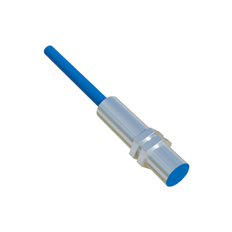
Three-wire proximity sensors are predominantly available in two sensing technologies: inductive and capacitive. Inductive sensors generate an oscillating electromagnetic field from a coil and ferrite core. When a metallic object enters this field, it induces eddy currents that dampen the oscillation, triggering the sensor's internal switch. Capacitive sensors, on the other hand, create an electrostatic field and detect changes in capacitance caused by the presence of any material, including non-metals, liquids, or granular substances. The core electronics within the sensor housing continuously monitor this field. Upon detection, a solid-state switching element (like a transistor) changes state, altering the signal on the dedicated output wire.
Wiring Configuration and Polarity
The three wires are typically color-coded for easy identification: brown for positive DC supply (V+), blue for common ground or negative (V- or 0V), and black for the output signal. A critical distinction lies in the output type, which defines the wiring logic. In a 3-wire sensor, the output transistor can be configured as either NPN (sinking) or PNP (sourcing). An NPN sensor switches the black output wire to connect to the negative (blue) line when active, effectively "sinking" current to ground. Conversely, a PNP sensor switches the black output wire to connect to the positive (brown) line when active, "sourcing" current from the supply. The choice between NPN and PNP must match the input circuit requirements of the connected controller to ensure proper operation and avoid damage.
Output Types: NPN vs. PNP
Understanding the difference between NPN and PNP outputs is paramount for correct system integration. NPN (Negative-Positive-Negative) sensors are commonly used in Asian and European markets with PLCs that have sinking input modules. When the sensor detects a target, the output transistor activates, allowing current to flow from the load (like the PLC input) into the sensor and out to ground. PNP (Positive-Negative-Positive) sensors are often preferred in North America and interface with sourcing input modules. Here, upon detection, the sensor provides a positive voltage signal from its output wire to the load. Selecting the wrong type will result in a non-functional circuit. Many modern sensors feature selectable or universal outputs to simplify inventory and installation.
Key Advantages in Industrial Settings
The 3-wire design offers significant benefits over 2-wire alternatives. Firstly, they provide a physically separate output wire, allowing for a wider range of output currents and lower leakage currents when in the "off" state. This results in more reliable switching, especially with sensitive PLC inputs. Secondly, they enable both normally open (NO) and normally closed (NC) output logic, offering flexibility in control circuit design. Their solid-state construction ensures high switching speeds, often in the kilohertz range, and exceptional longevity with no moving parts to wear out. They are also highly resistant to environmental factors like vibration, dust, and moisture, particularly those with IP67 or higher ratings.
Typical Installation and Wiring Practices
Proper installation is crucial for optimal performance. The sensor must be mounted securely to minimize vibration. It is essential to maintain the specified sensing distance and ensure the target material and size are within the sensor's specifications. When wiring, always disconnect power. Connect the brown wire to the positive DC supply (typically 10-30V DC) and the blue wire to the common ground. The black output wire connects to the load (e.g., a PLC input terminal). A protective fuse or circuit breaker in the supply line is recommended. For noise immunity in electrically noisy environments, use shielded cable and ground the shield at the controller end only. Always consult the manufacturer's datasheet for specific voltage ranges, current ratings, and connection diagrams.
Common Applications Across Industries
The application scope for 3