Introduction to Proximity Sensor Fundamentals
Proximity sensors are non-contact electronic devices designed to detect the presence or absence of an object within a specified sensing range without physical contact. Their operation hinges on the disturbance of an electromagnetic field, acoustic wave, or light beam. The core advantage lies in their ability to function reliably in harsh industrial environments where dirt, oil, or mechanical wear would compromise contact-based switches. These sensors are fundamental components in automation, robotics, safety systems, and countless manufacturing processes, providing critical input for control systems to initiate actions like counting, positioning, inspection, or automated machine control. The absence of moving parts in most types contributes to their long operational life and minimal maintenance requirements.
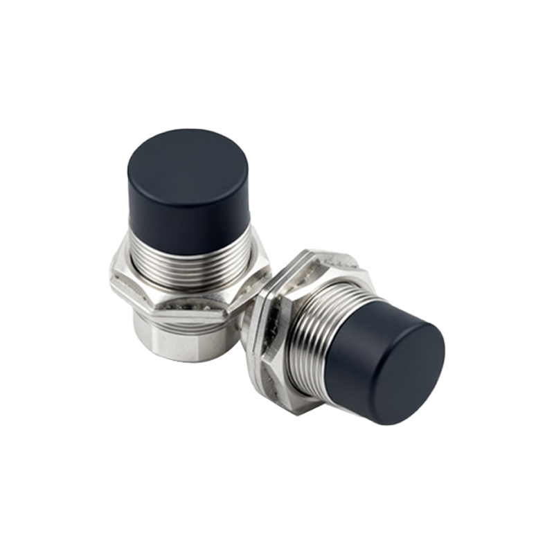
Core Sensing Element and Oscillator Circuit
At the heart of an inductive or capacitive proximity sensor lies the sensing coil or electrode, which is the primary structural component. This element is connected to a high-frequency oscillator circuit. In an inductive sensor, the coil generates a high-frequency electromagnetic field that radiates from the active face of the sensor. When a metallic target enters this field, eddy currents are induced on the target's surface. These currents draw energy from the oscillator, causing a reduction in its oscillation amplitude. This change is the primary detectable signal. The design of the coil—its size, winding pattern, and core material—directly determines the sensor's nominal sensing distance and electromagnetic characteristics. Shielding around the coil can focus the field, making the sensor less susceptible to lateral metal interference.
Signal Conditioning and Evaluation Circuitry
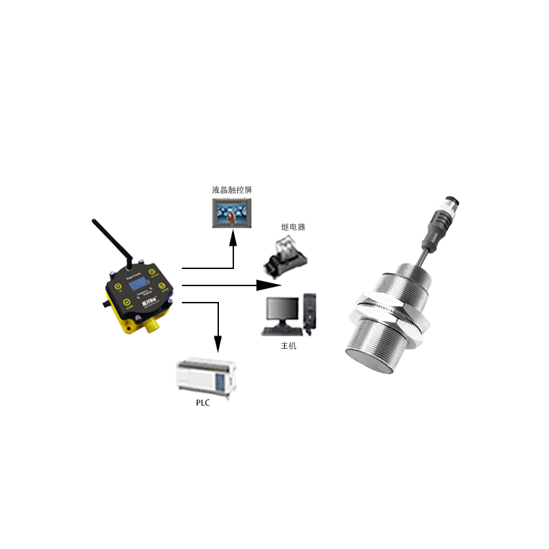
The raw signal from the oscillator—typically a change in amplitude or frequency—is weak and requires precise conditioning. This is the role of the evaluation or trigger circuit. This circuitry filters out electrical noise, compensates for temperature variations, and stabilizes the signal against supply voltage fluctuations. It compares the processed signal against a pre-set threshold or trigger level. Once the signal strength crosses this threshold (indicating a target is within range), the evaluation circuit triggers a state change in the sensor's output. Modern sensors often incorporate microcontrollers or application-specific integrated circuits (ASICs) for advanced functions like programmable sensing distances, output delays (on/off delay), and diagnostic capabilities like short-circuit and overload protection.
Output Switching Stage and Configuration
The output stage is the component that interfaces the sensor with the external control system, such as a PLC (Programmable Logic Controller). Upon a detection event signaled by the evaluation circuit, the output stage switches its state. The two primary electronic output types are NPN (sinking) and PNP (sourcing) transistor configurations for DC sensors, and solid-state or electromechanical relay outputs for AC/DC sensors. The output transistor or relay is a critical structural element, housed within the sensor body, and is rated for specific voltage, current, and load types (resistive, inductive). Protection elements like flyback diodes for inductive loads or snubber circuits for AC loads are often integrated into this stage to ensure longevity and prevent damage from voltage spikes.
Housing, Encapsulation, and Environmental Protection
The physical housing is a vital structural aspect that ensures reliability. It is typically constructed from materials like nickel-plated brass, stainless steel (V2A, V4A), or industrial-grade plastics like PBT or PPS, chosen for mechanical strength and chemical resistance. The active sensing face is often made of a specific material, such as PTFE for weld-field immunity in inductive sensors, that allows the electromagnetic field to pass while protecting the internal coil. Critical to longevity is the encapsulation or potting process, where the internal electronic assembly is completely embedded in a resin compound. This protects against moisture, vibration, shock, and corrosive agents. The housing's design also incorporates standardized mounting threads (e.g., M8, M12, M18, M30) and connection styles (e.g., cable exit, quick-disconnect M12 connector) for easy installation.
Target Material and Sensing Range Considerations
While not part of the sensor's internal structure, the target's properties are a critical external factor in the sensor's operational structure. For inductive sensors, the sensing distance is standardized for mild steel (Fe360). For other metals like stainless steel, aluminum, or copper, a reduction factor must be applied, as these materials induce eddy currents with different efficiencies. The target's size, shape, and approach direction also affect performance; a standard target is typically a square of ferrous metal with a side length equal to the sensor's face diameter or three times its nominal sensing distance. Understanding this interaction is essential for correct sensor selection and mounting in the final application structure.