Introduction to Speed Sensing Proximity Switches
Speed sensing proximity switches are fundamental components in modern industrial automation and motion control systems. These devices serve a dual purpose: they detect the presence or absence of a target object without physical contact, and they measure the rotational or linear speed of that target. Operating on principles of electromagnetic induction, capacitance, or magnetism, these sensors provide critical data for process control, safety monitoring, and equipment diagnostics. Their non-contact nature ensures high reliability, long service life, and minimal maintenance, making them indispensable in harsh environments where mechanical wear or contamination is a concern. From conveyor belts and motor shafts to turbine blades and vehicle axles, their applications span virtually every sector of manufacturing and transportation.
Core Operating Principles: Inductive, Capacitive, and Magnetic
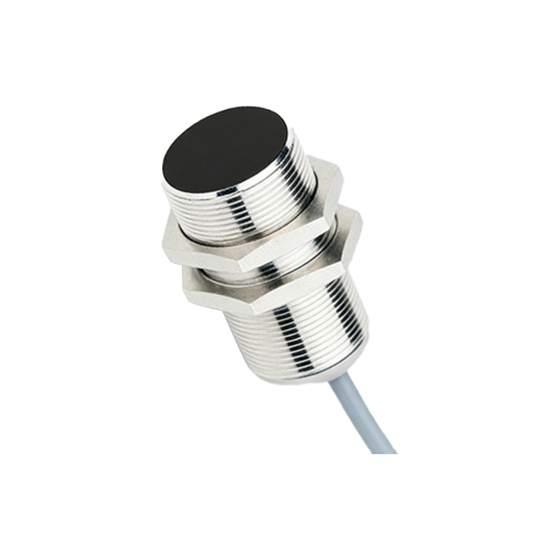
The most common type is the inductive proximity switch. It contains an oscillator circuit that generates a high-frequency electromagnetic field at its sensing face. When a metallic target enters this field, eddy currents are induced on the target's surface. This causes a change in the oscillation amplitude, which is detected by a threshold circuit, triggering a solid-state output switch. For speed sensing, a toothed wheel or a disc with protrusions is attached to the rotating shaft. Each tooth or protrusion passing the sensor face causes a pulse in the output. By counting these pulses over a known time period, the rotational speed (RPM) can be accurately calculated. Capacitive sensors work on a similar principle but detect changes in capacitance caused by both metallic and non-metallic materials, making them versatile for different target types. Magnetic proximity switches, or Hall-effect sensors, detect changes in a magnetic field, typically from a magnet embedded in or attached to the target.
Key Components and Signal Generation
Internally, a typical inductive speed sensor comprises several key components: a ferrite core with a coil, the oscillator circuit, a demodulator, a trigger circuit, and an output amplifier. The sensing face is precisely designed to shape the electromagnetic field. For speed measurement applications, the target is engineered with a specific number of teeth, gaps, or notches to create a clean, consistent pulse train. The quality of this pulse signal is paramount. Factors such as target material, size, shape, and the air gap between the target and sensor directly affect the signal strength and stability. The output from the sensor is typically a square wave pulse signal (PNP or NPN), a voltage analog signal (0-10V), or a current analog signal (4-20mA), which is then fed into a programmable logic controller (PLC), frequency counter, or dedicated tachometer for processing.
Critical Performance Parameters and Selection Criteria
Selecting the right speed sensing proximity switch requires careful consideration of several parameters. The sensing distance, or nominal range, must be suitable for the application's mechanical setup. Switching frequency defines how quickly the sensor can respond to incoming targets and is crucial for measuring high speeds; a sensor with a 5 kHz switching frequency can theoretically measure up to 300,000 RPM for a single-pulse-per-revolution setup. Environmental factors like temperature rating, ingress protection (IP) class against dust and water, and resistance to chemicals or oils are vital for durability. The target material and size must be compatible with the sensor's technology. For inductive sensors, steel targets provide the longest sensing range, while aluminum or copper requires a reduced range. Finally, the output type must match the input requirements of the subsequent control system.
Application Examples in Industrial Systems
In practice, these sensors are deployed in myriad ways. On a production line, they monitor the speed of a conveyor to synchronize processes or detect slippage. In motor control, they provide feedback for closed-loop variable frequency drive (VFD) systems, ensuring precise speed regulation. They act as overspeed or underspeed detectors on fans, pumps, and gearboxes, triggering alarms or shutdowns to prevent damage. In the automotive industry, they are used as wheel speed sensors for anti-lock braking systems (ABS) and crankshaft position sensors for engine timing. Each application demands specific mounting, alignment, and shielding considerations to ensure immunity from electrical noise and mechanical vibration, which could otherwise corrupt the speed signal.
Installation, Alignment, and Troubleshooting Tips
Proper installation is critical for reliable operation. The sensor must be mounted securely to prevent vibration from altering the air gap. Alignment with the target (e.g., the teeth of a gear) must be precise, typically perpendicular to the direction of movement. The recommended air gap is usually 50% to 80% of the nominal sensing distance to account for mechanical tolerances and thermal expansion. Shielding and using twisted-pair cables are essential practices to