Understanding Proximity Switch Sensor Plug Types
Proximity switch sensor plugs come in various configurations, typically categorized by pin count, shape, and connection method. Common types include M8, M12, and M16 threaded connectors, with 3-pin or 4-pin setups being standard in industrial applications. The M12 plug, for instance, is widely used for its compact size and durability, while M16 variants suit environments requiring higher current capacity. Each plug type corresponds to specific sensor functions—such as NPN (sinking) or PNP (sourcing) outputs—and incorrect pairing can lead to malfunction. Before wiring, identify the plug's specifications from the sensor datasheet, noting the pin assignments for power supply, output signal, and ground. This step ensures compatibility with control systems like PLCs or relays, preventing electrical mismatches.
Essential Tools and Safety Precautions
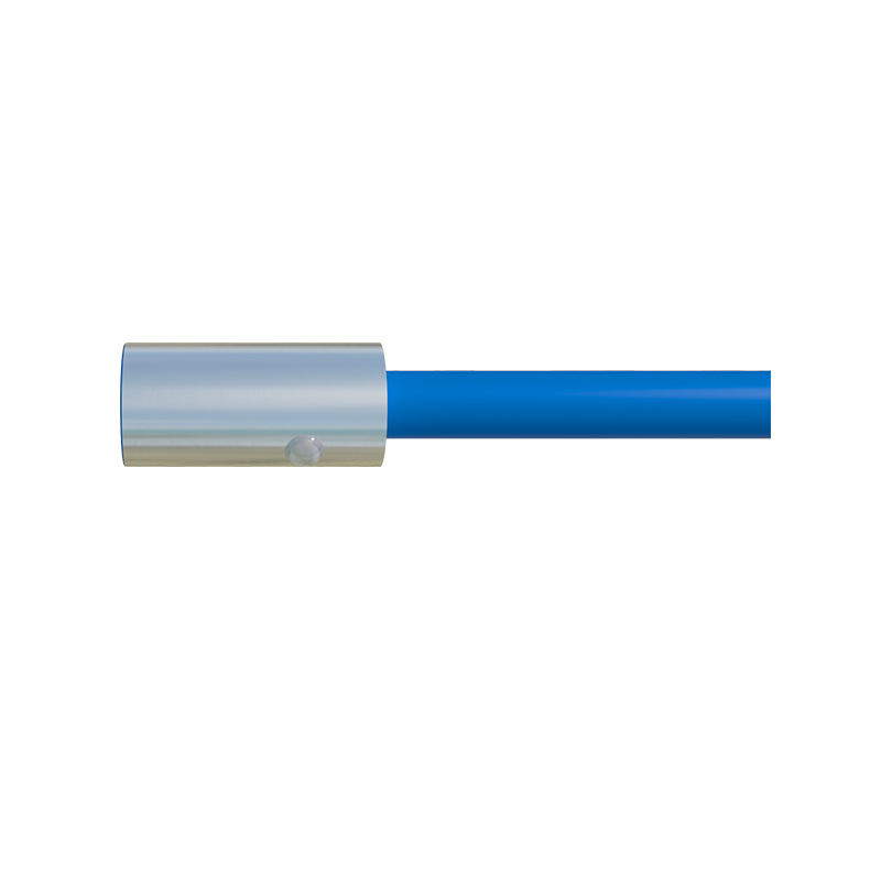
Wiring proximity sensor plugs demands precision tools and adherence to safety protocols. Gather a wire stripper, crimping tool, screwdriver, multimeter, and heat shrink tubing. Always disconnect power from the circuit before starting to avoid shocks or short circuits. Wear insulated gloves and safety glasses, especially in high-voltage settings. Verify the sensor's operating voltage (e.g., 10-30V DC) and current ratings to prevent overload. Use a multimeter to check for continuity and voltage levels, ensuring the wiring environment is dry and free from debris. Proper grounding of equipment minimizes electromagnetic interference, which can affect sensor accuracy.
Step-by-Step Wiring Procedure
Begin by stripping the insulation from the sensor cable wires, exposing about 5-7mm of conductor. Match the wire colors to the plug pins: typically, brown for positive voltage (+V), blue for ground (0V), black for output signal, and white for complementary output in 4-pin models. Insert each wire into the corresponding pin slot of the plug housing, securing them with crimp connectors or screws. For M12 plugs, twist the connector clockwise until it locks, ensuring a watertight seal in IP67-rated units. After assembly, test the connection by temporarily powering the system and observing the sensor's indicator LED. If it lights up, the wiring is functional; otherwise, recheck pin alignments.
Troubleshooting Common Wiring Issues
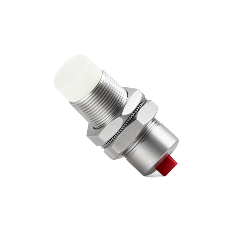
Faulty wiring often manifests as sensor failure, erratic signals, or no output. Start by inspecting for loose connections, corrosion, or damaged wires—tighten any loose screws and replace frayed cables. Use a multimeter to measure voltage across the power pins; a reading below the specified range may indicate a short circuit. For NPN sensors, ensure the output pin connects to the load's negative side, while PNP types require positive linkage. Interference from nearby motors or cables can cause noise; shield the sensor cable or reroute it away from power lines. Consult the manufacturer's wiring diagram to confirm polarity, as reverse connections can permanently damage the sensor.
Best Practices for Long-Term Reliability
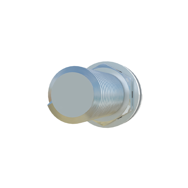
To extend the lifespan of proximity sensor plugs, implement routine maintenance and correct installation habits. Apply dielectric grease to plug contacts to prevent oxidation in humid conditions. Use strain relief brackets to avoid tension on cables, which can loosen connections over time. Label each wire and plug with tags for easy identification during repairs. Periodically clean plugs with isopropyl alcohol to remove dust or oil buildup. In harsh environments, opt for shielded cables and industrial-grade connectors rated for high temperatures or vibrations. Document wiring layouts in system logs, updating them after any modifications to streamline future troubleshooting.