Understanding the Basic Principle
The core function of an escalator photoelectric sensor is to detect the presence or absence of an object, typically a passenger or an obstruction, by utilizing a beam of light. The most common configuration is the through-beam type, where a transmitter and a receiver are positioned opposite each other. The transmitter emits a constant or modulated infrared (IR) light beam. When this beam is uninterrupted, the receiver detects it, and the sensor outputs a "clear" signal. When an object breaks the beam, the receiver's signal drops, triggering an "object detected" signal to the escalator's control system. This simple yet reliable principle forms the backbone of safety and operational control in modern escalators.
Selecting Core Components
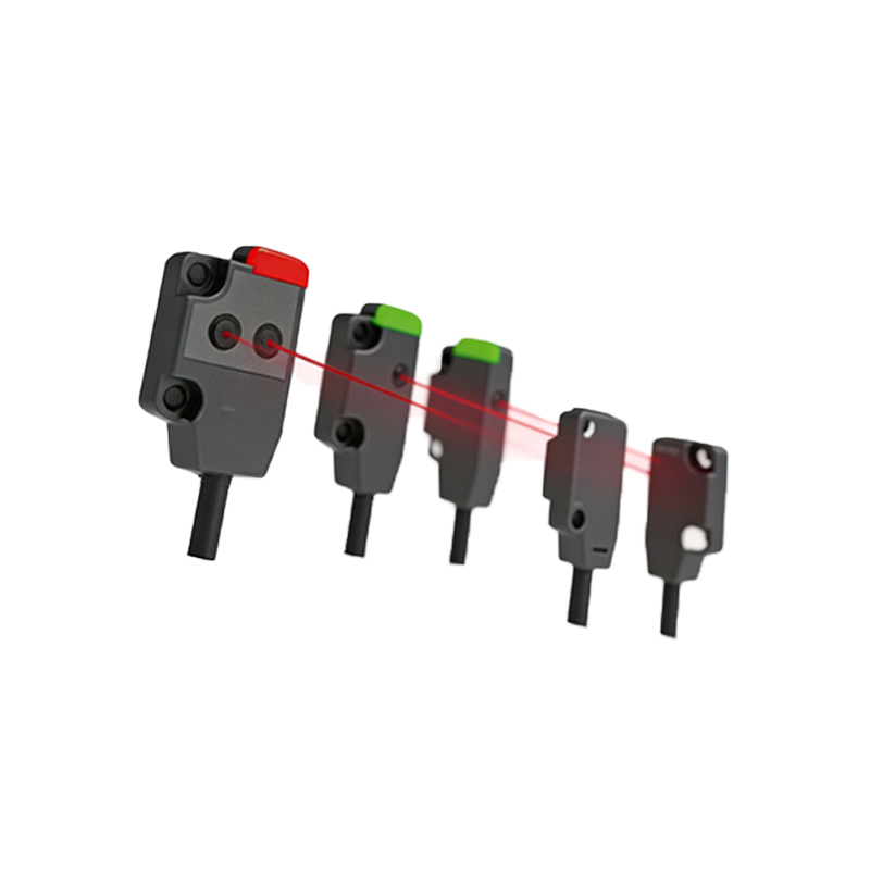
The quality of the final sensor assembly hinges on careful component selection. First, choose a high-quality infrared LED as the transmitter. Key parameters include wavelength (typically 850nm or 940nm for minimal ambient light interference), viewing angle, and optical output power. For the receiver, a phototransistor or a photodiode with a matching spectral response is essential. Consider components with built-in daylight filters to enhance noise immunity. You will also need a stable power supply circuit, operational amplifiers (op-amps) for signal conditioning, a comparator circuit to create a clean digital output, and durable housing materials rated for the escalator's environment (encompassing dust, vibration, and temperature fluctuations).
Designing the Transmitter Circuit
The transmitter circuit's primary goal is to provide a stable, modulated IR light source. Direct current driving of the LED is not recommended due to susceptibility to ambient light changes and potential interference from other IR sources. Instead, design a circuit that pulses the LED at a specific frequency (e.g., 1kHz to 10kHz). This can be achieved using a 555 timer IC or a microcontroller oscillator. Modulation allows the receiver circuit to filter out all light signals except the specific frequency, dramatically improving reliability. Include a current-limiting resistor to protect the LED and ensure consistent output over its lifespan.
Designing the Receiver and Signal Processing Circuit
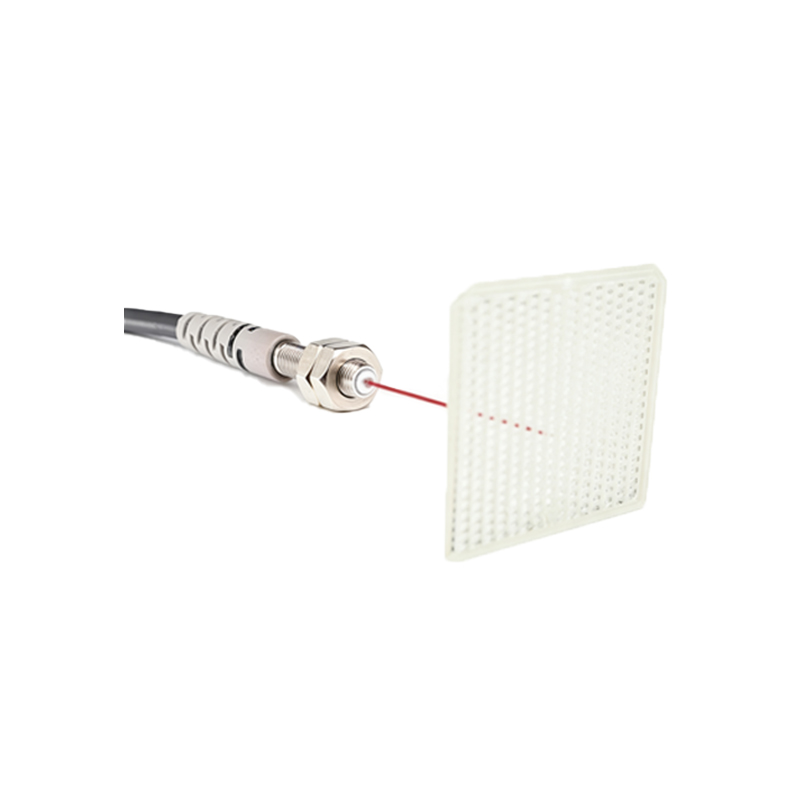
The receiver circuit must accurately detect the modulated signal. The phototransistor converts the pulsed IR light into a small, pulsed electrical current. This weak signal first passes through a transimpedance amplifier (using an op-amp) to convert it into a usable voltage. Next, the signal goes through a band-pass filter tuned to the transmitter's modulation frequency. This stage is critical for rejecting background light (like fluorescent lamp flicker) and other noise. The clean, amplified signal is then fed into a comparator circuit. The comparator compares the signal voltage against a preset threshold. If the signal is above the threshold (beam intact), the output is high; if it drops below (beam broken), the output switches to low, providing a clear digital signal to the PLC or control board.
Mechanical Housing and Alignment
Robust mechanical design is as important as the electronics. The transmitter and receiver must be housed in separate, rugged enclosures, typically made of metal or high-grade industrial plastic. These housings should have precisely machined lenses or windows to protect the optical components while allowing clear light passage. They must be IP-rated (e.g., IP54 or higher) to withstand dust and moisture. The most critical mechanical aspect is providing a secure and precise means for alignment. Incorporate adjustable mounting brackets or alignment screws. During installation, use alignment tools to ensure the transmitter beam is perfectly centered on the receiver's active area for maximum signal strength and detection accuracy.
Testing and Calibration Procedures
Before deployment, rigorous testing is mandatory. First, perform bench testing: power the units and verify the output signal state changes reliably when an object interrupts the beam at various distances within the specified range. Use an oscilloscope to observe the signal integrity before and after the comparator. Next, simulate environmental challenges, such as shining a bright work light directly at the receiver to test ambient light rejection. Finally, calibrate the system. The primary calibration point is the comparator's threshold voltage. Adjust it so that the output switches reliably with the intended object (e.g., a test rod of a specific diameter) at the maximum operational distance, while not being triggered by dust or small insects. Document all test results.
Installation and Maintenance Guidelines
Install the sensor pair on the escalator's skirt or balustrade at the designated entry and exit points, ensuring a clear, unobstructed line of sight. Securely fasten the housings to prevent movement from vibration. After physical installation, perform a final alignment check. Connect the sensor's output to the control system and verify its operation by repeatedly passing a test object through the beam. For maintenance, establish a regular schedule to clean the optical lenses from accumulated dust and grime, which can attenuate the signal. Periodically check the mechanical fasteners for tightness and re-verify the output signal's integrity. Log all maintenance activities to ensure long-term operational safety and reliability.