Understanding Proximity Sensor Fundamentals
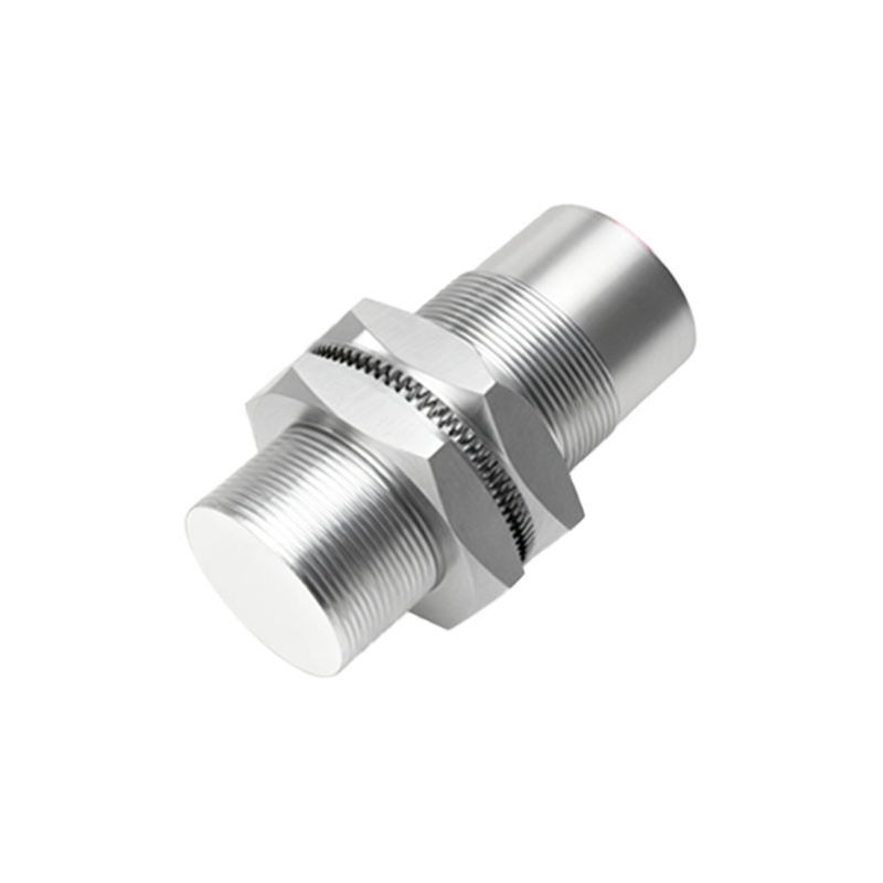
Proximity sensors are vital components in industrial automation, detecting the presence or absence of an object without physical contact. The core principle involves generating an electromagnetic field or a beam of light. When a target object enters this field, it causes a change in the sensor's oscillation or light reception, triggering an output signal. The key parameter for adjustment is the sensing distance, also known as the operating distance. This is the maximum distance at which the sensor can reliably detect a standard target. It is crucial to note that the effective sensing distance can be influenced by factors such as the target material, size, shape, and environmental conditions like temperature and the presence of contaminants. A thorough understanding of these fundamentals is the first step toward precise adjustment and reliable operation in any application.
Pre-Adjustment Preparation and Safety
Before initiating any adjustment procedure, comprehensive preparation is essential to ensure safety and accuracy. First, always consult the sensor's specific datasheet and installation manual provided by the manufacturer. These documents contain critical information regarding the nominal sensing distance, electrical specifications, adjustment methods, and environmental limits. Second, implement proper lockout/tagout (LOTO) procedures for the machinery or system to isolate energy sources and prevent accidental startup. Visually inspect the sensor for any physical damage, corrosion, or loose connections. Ensure the sensor is correctly mounted and aligned relative to the expected path of the target object. Cleaning the sensing face of any oil, dust, or debris is also a critical step, as contaminants can significantly reduce the effective sensing range and cause erratic behavior.
Methods for Adjusting Sensing Distance
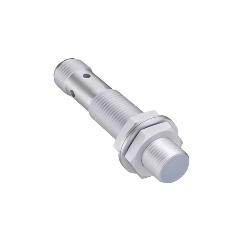
Most modern proximity sensors feature built-in adjustment mechanisms, primarily through a potentiometer or via teach-in functions. For sensors with a potentiometer, use a small, non-conductive screwdriver to turn the adjustment screw. Typically, rotating clockwise increases the sensitivity (and thus the sensing distance), while counterclockwise rotation decreases it. Make incremental adjustments and test the sensor's response after each turn. For advanced sensors with teach-in capability, the process often involves presenting the target at the desired maximum detection distance and activating a "set" or "teach" button, either physically on the sensor or via a remote signal. This method automatically calibrates the sensor to that specific distance. Some programmable logic controller (PLC)-based systems allow for sensitivity adjustment through software parameters, offering remote and precise control.
Calibration and Testing Procedures
After making initial adjustments, a rigorous calibration and testing phase is mandatory. Begin by using the standard target specified in the datasheet, usually a square of mild steel of defined thickness and side length. Gradually move the target toward the sensor's face until the output activates. Mark this point as the actual sensing distance. Repeat this process several times to ensure consistency and repeatability. It is often recommended to set the operational sensing distance at 70-80% of the maximum rated distance to account for variables like temperature drift, voltage fluctuations, and target wear. Test the sensor with the actual application target under normal operating speeds and conditions. Verify that the sensor does not falsely trigger due to background objects, vibration, or electrical noise, which may require further sensitivity reduction.
Troubleshooting Common Adjustment Issues
Several common issues can arise during or after adjustment. If the sensor cannot achieve the required sensing distance, verify the target material and size; non-ferrous metals and smaller targets require sensors specifically designed for them (e.g., capacitive or ultrasonic). Excessive sensing distance or instability might indicate a need for shielding from adjacent metal objects or other sensors causing mutual interference. Ensure proper grounding and use shielded cables to mitigate electrical noise. If the adjustment potentiometer seems to have no effect, the sensor may be faulty or operating outside its voltage range. Consistently short sensing distances could be caused by a dirty sensing face, incorrect mounting (e.g., flush vs. non-flush), or a degraded internal oscillator. Methodical troubleshooting is key to resolving these performance hiccups.
Best Practices for Long-Term Stability
To maintain the adjusted sensing performance over the long term, adhere to a set of best practices. Regularly schedule preventive maintenance to clean the sensor and inspect for mechanical damage or loosened mounts. Monitor the system's power supply voltage, as significant drops can reduce sensing distance. Implement environmental protections such as enclosures or coatings if the sensor is exposed to moisture, chemicals, or extreme temperatures. Keep a log of adjustment settings and performance tests for critical applications to track any drift over time. Finally, always use sensors with an appropriate IP rating for the environment and ensure they are not subjected to physical impact or stress beyond their specifications. Proactive maintenance ensures sustained reliability and minimizes unplanned downtime.