Understanding Proximity Sensor Fundamentals
Before initiating the calibration process, a thorough understanding of the sensor's operating principle is paramount. Proximity sensors, whether inductive, capacitive, or photoelectric, function by detecting the presence or absence of a target object without physical contact. Inductive sensors detect metallic objects, capacitive sensors detect both metallic and non-metallic materials, and photoelectric sensors use light beams. The core output is typically a switching signal. Incorrect calibration can lead to false triggers, missed detections, or reduced operational lifespan. Always begin by consulting the manufacturer's datasheet for specific parameters such as sensing distance, supply voltage, output type (PNP/NPN, NO/NC), and environmental ratings. Ensure the power supply is stable and matches the sensor's specifications to prevent damage during setup.
Pre-Calibration Safety and Preparation
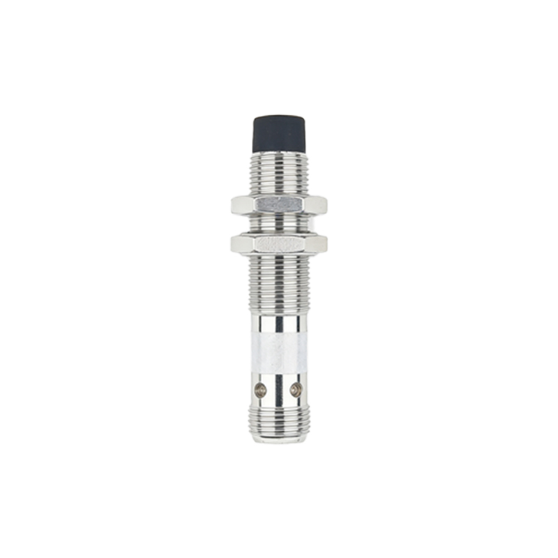
Safety is the first priority in any industrial setting. De-energize the circuit or equipment where the sensor is installed. If testing in place, implement appropriate lockout-tagout (LOTO) procedures. Gather the necessary tools: a multimeter for voltage and continuity checks, the target object specified for the sensor (e.g., a specific grade of steel for inductive types), and any manufacturer-provided calibration tools or indicators. Visually inspect the sensor for physical damage, corrosion, or contamination. Clean the sensing face with a soft, dry cloth to remove any oil, dust, or metal shavings that could interfere with performance. Verify the mechanical mounting is secure and that the sensor is correctly aligned with the expected path of the target object.
Electrical Wiring and Connection Verification
Correct wiring is critical for reliable operation. For a standard 3-wire DC sensor, identify the brown wire (typically +V), blue wire (0V or common), and black wire (output signal). Connect the brown and blue wires to the corresponding DC power supply terminals. For PNP (sourcing) sensors, the black wire provides a positive voltage when activated; for NPN (sinking) sensors, it provides a path to ground. Use the multimeter to confirm power is present at the sensor terminals. Check for proper grounding and shield the cable if it runs parallel to high-voltage lines to prevent electrical noise interference, a common cause of erratic behavior. Ensure the load (e.g., PLC input, relay coil) is connected in series with the sensor's output wire and the appropriate power rail.
Setting the Sensing Distance and Sensitivity
Most modern proximity sensors feature a potentiometer or a teach-in function for adjusting sensitivity or the effective sensing distance. Power the sensor. Slowly bring the standard target object toward the sensing face along the axis. Observe the sensor's indicator LED (if equipped). For sensors with a potentiometer, use a small screwdriver to adjust it. Turn clockwise to increase sensitivity (longer sensing range) or counterclockwise to decrease it. The goal is to set the sensing point so that the sensor reliably activates at the desired position, with a safety margin of approximately 10-20% of the rated sensing distance to account for mechanical tolerances, temperature drift, and supply voltage variations. Avoid setting the sensitivity at the absolute maximum, as this can cause instability.
Testing and Validating Sensor Response
After the initial adjustment, perform comprehensive dynamic testing. Move the target object repeatedly through the sensing zone at the operational speed. Monitor the sensor's output using a multimeter, an oscilloscope, or the PLC's diagnostic software. The output signal should be clean and switch crisply without chatter or delay. Test with the actual production object if it differs from the calibration target, as material composition, size, and color can affect detection. Conduct tests under worst-case conditions, such as with a dirty target, at temperature extremes, or with induced vibration. Verify the sensor does not activate due to nearby non-target objects (e.g., machine frames, passing personnel) to ensure immunity from false triggers.
Troubleshooting Common Calibration Issues
If the sensor fails to perform as expected, follow a logical troubleshooting sequence. First, re-check all electrical connections and power supply voltage. If the output is always ON or OFF, swap the sensor with a known-good unit to isolate the problem. For intermittent operation, investigate environmental factors: electrical noise, adjacent sensors interfering with each other (mutual interference), or accumulation of conductive debris on a capacitive sensor's face. For inductive sensors, ensure the target material is within the specified type and size. A sensing distance that is too short may indicate a problem with the oscillator circuit or a weakened magnetic field. Always cross-reference symptoms with the troubleshooting chart in the sensor manual.