Introduction to Reflective Photoelectric Sensors
Reflective photoelectric sensors are fundamental components in modern industrial automation and control systems. These devices operate on a simple yet effective principle: they emit a beam of light, typically from an LED, and detect the light that is reflected back from a target object. Unlike through-beam sensors that require separate emitter and receiver units, the reflective type integrates both elements into a single housing. This compact design makes them highly versatile for applications where space is limited or where mounting two separate units is impractical. The core functionality hinges on the interruption or variation of the reflected light beam, which is then converted into an electrical signal by the receiver, usually a phototransistor or photodiode. This signal change triggers an output, enabling the sensor to perform tasks such as object detection, counting, and positioning with high reliability and speed.
Key Components and Internal Schematic
Understanding the internal schematic is crucial for proper selection and troubleshooting. The primary components include the light-emitting element, the light-receiving element, signal processing circuitry, and the output stage. The emitter circuit typically involves a current-limiting resistor in series with an infrared or visible light LED to ensure stable light output. The receiver circuit features a phototransistor whose conductivity changes in proportion to the intensity of the received reflected light. This analog signal is then fed into a comparator or amplifier IC within the sensor. The comparator compares the signal level against a preset threshold, which is often adjustable via a potentiometer for sensitivity control. Once the threshold is crossed, the output stage—which can be an NPN/PNP transistor, a relay, or a solid-state switch—activates, providing a clean digital signal (ON/OFF) to the connected controller, such as a PLC.
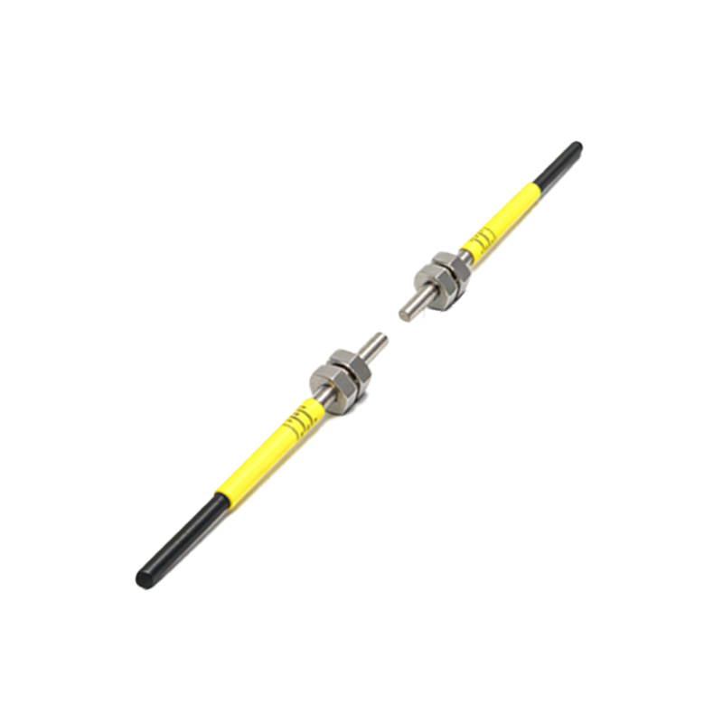
Schematic Diagram Analysis and Operation
A detailed schematic diagram visually maps the electrical connections and interactions between these components. The diagram starts with the power supply pins (Vcc and GND). The emitter leg shows the LED (D1) anode connected to Vcc through resistor R1. The receiver section shows the phototransistor (Q1) with its collector linked to Vcc via a pull-up resistor (R2) and its emitter connected to ground. The voltage at the collector node, which varies with light intensity, is the key signal. This point connects to the non-inverting input of an operational amplifier (configured as a comparator, U1:A). A voltage divider network (R3 and variable resistor VR1) sets the reference voltage at the inverting input. The output of the comparator drives the base of an output transistor (Q2), which switches the load connected to the OUT terminal. This arrangement ensures that only a sufficient amount of reflected light, indicating the presence of a target, causes the output to change state.
Critical Design Considerations and Parameters
Several parameters must be carefully considered when interpreting or designing based on a reflective sensor schematic. Sensing distance is paramount and is influenced by the LED's power, the phototransistor's sensitivity, and the target's reflectivity. The schematic's resistor values (R1, R2) directly impact current and thus these factors. Response time is determined by the speed of the phototransistor and the comparator circuit. The inclusion of a hysteresis circuit, often via positive feedback around the comparator (e.g., resistor R4), is a common feature in schematics to prevent output oscillation when the detected signal is near the threshold. Furthermore, protection components like capacitors for noise filtering and transient voltage suppression diodes are often present in robust schematics to ensure stable operation in electrically noisy industrial environments.
Application-Specific Circuit Variations
The basic schematic adapts to various specialized applications. For background suppression sensors, the schematic incorporates a position-sensitive detector (PSD) and more complex triangulation circuitry to ignore distant background objects. For color-mark sensors, the schematic includes multiple receivers with filters or uses a specialized IC to distinguish contrast based on color. Analog output versions replace the digital comparator with a linear amplifier circuit, providing a voltage or current output proportional to the distance or reflectivity of the target. These variations are clearly detailed in their respective schematic diagrams, showing additional operational amplifiers, reference voltage sources, and sometimes integrated microcontroller units for advanced signal processing and programmability.
Troubleshooting Using the Schematic Diagram
The schematic is an indispensable tool for diagnostics. Common issues include no output, erratic operation, or shortened sensing range. Using a multimeter, an engineer can trace the circuit: first, verify power (Vcc) at the IC and transistor pins. Next, check if the emitter LED is functioning by measuring voltage across its current-limiting resistor. For the receiver, monitor the voltage at the phototransistor's collector while exposing it to light; it should vary. If it does not, the phototransistor may be faulty. If the signal varies but the output doesn't switch, the problem may lie in the comparator stage (check reference voltage set by VR1) or the output transistor. The schematic provides a logical roadmap for this systematic isolation of faults, saving valuable time during maintenance.
Conclusion and Integration Best Practices
In conclusion, a thorough understanding of the reflective photoelectric sensor schematic diagram empowers engineers to effectively integrate, calibrate, and maintain these devices. When integrating into a larger system, always refer to the manufacturer's datasheet for the complete schematic and absolute maximum ratings. Ensure the electrical characteristics of the sensor's output (sourcing vs. sinking, voltage, current) are compatible with the input module of the controller. Proper wiring as per the schematic—paying attention to polarity and load connections—is essential. Finally, environmental factors like ambient light, dust, and the target material's surface properties must be considered during installation, as they directly affect the performance predicted by the electrical design. Mastery of the schematic translates to optimized and reliable sensor application across countless automation scenarios.