Introduction to U-Shaped Photoelectric Sensors
U-shaped photoelectric sensors, also known as through-beam sensors, are fundamental components in industrial automation and control systems. These devices consist of two separate units: a transmitter and a receiver, housed in a U-shaped bracket that aligns them perfectly opposite each other. The transmitter emits a beam of light, typically infrared or visible LED, which is detected by the receiver. When an object passes through the gap of the U-shape, it interrupts this light beam, causing the sensor to trigger a switching action. This simple yet highly reliable principle makes U-shaped sensors ideal for detecting the presence, absence, or position of objects on production lines, conveyor belts, and in packaging machinery. Their through-beam design offers the longest sensing range and highest excess gain among photoelectric sensor types, ensuring stable operation even in environments with dust, dirt, or minor misalignment. The control table for these sensors is the critical interface that dictates their operational parameters and response characteristics.
Key Components of the Control Table
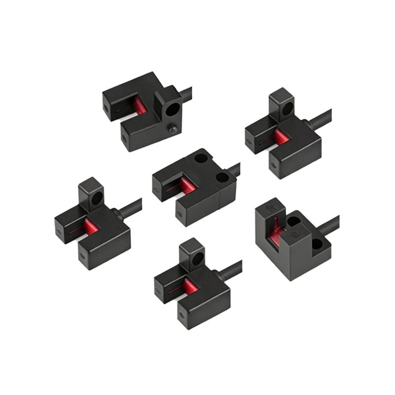
The control table for a U-shaped photoelectric sensor is not a physical table but a conceptual framework or specification sheet detailing its configurable settings and electrical characteristics. Understanding this "table" is essential for proper integration. Primary components include the power supply requirements, typically ranging from 10-30V DC. The output configuration is crucial, specifying whether the sensor provides a Normally Open (NO) or Normally Closed (NC) signal, and the type of output transistor (NPN or PNP) to match the PLC or controller input. The response time, often in milliseconds, defines how quickly the sensor can detect an interruption and change its output state. This is vital for high-speed applications. The control table also specifies the light source type, its modulated frequency to avoid interference from ambient light, and the rated sensing distance or gap width of the U-shaped housing. Environmental ratings like IP67 for dust and water resistance are also listed, ensuring suitability for harsh industrial conditions.
Wiring and Electrical Interface
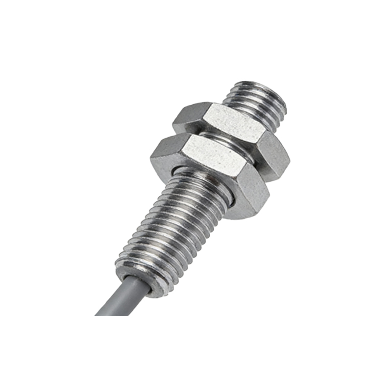
Correct wiring as per the control table is paramount for safety and functionality. A standard three-wire DC sensor has brown (V+), blue (V- or 0V), and black (output signal) wires. The control table explicitly defines the connection: the brown wire connects to the positive DC supply, blue to the negative or common, and the black wire carries the switched output to the load (e.g., a PLC input module). For a PNP sensor (sourcing), the black wire outputs a positive voltage when activated. For an NPN sensor (sinking), it switches the ground connection. The table specifies the maximum load current the output can handle, usually around 100-200mA, which protects the sensor from damage. It also indicates the presence of a status LED, which provides visual indication of power and output state, a key feature for troubleshooting. Miswiring can lead to sensor failure or damage to connected controllers, so adhering to the control table's wiring diagram is non-negotiable.
Configuration and Setting Adjustments
Modern U-shaped sensors often include configurable parameters beyond basic on/off operation. The control table outlines these adjustable settings. A common feature is the Light-On/Dark-On mode selection. In Light-On mode, the output activates when the receiver detects the light beam. In Dark-On mode, the output activates when the beam is blocked. This logical inversion is crucial for different control philosophies. Some advanced models offer a sensitivity adjustment or teaching function, allowing the user to set a threshold for detection, which can be useful for detecting translucent objects. The control table will define the method for adjustment, such as a potentiometer or a push-button teach-in procedure. Furthermore, it may specify options for output timing functions like a delay-on or delay-off, which can be essential for debouncing or ensuring stable signals in automated sequences.
Application-Specific Considerations
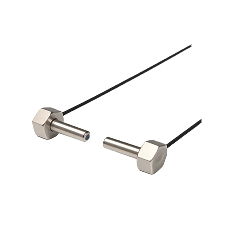
Selecting and configuring a U-shaped sensor based on its control table requires application analysis. For high-speed counting or sorting, the fast response time from the table is the top priority. In packaging, where films or clear bottles must be detected, the table's data on modulated light frequency and sensitivity adjustment is key to reliable operation. The mechanical specification of the U-shaped gap width determines the maximum size of object that can pass through, while the housing material (often metal or rugged plastic) ensures durability. In environments with significant vibration, the control table's data on shock resistance ensures longevity. For synchronized operations, some control tables mention synchronization cables that allow multiple sensors to operate on the same frequency without crosstalk. Always cross-reference the application requirements—object size, speed, material, and environmental challenges—with the specifications laid out in the sensor's control table.
Troubleshooting Using the Control Table
The control table is the first reference point for troubleshooting. If a sensor fails to operate, verify the power supply voltage and polarity against the table's specifications. Check the output load; exceeding the maximum current can damage the internal transistor. Use the status LED indication described in the table to diagnose issues: a steady power LED indicates good voltage, while a flickering or absent output LED during beam interruption suggests alignment problems or a dirty lens. The sensing range in the table assumes optimal conditions; actual range can be reduced by dirty environments. For intermittent operation, consult the table's data on ambient light immunity and ensure no other light source is emitting at the same modulation frequency. The environmental temperature range specified will indicate if thermal shutdown is a possibility. Methodically checking real-world conditions against the control table's benchmarks isolates most common failures.
Advantages and Industry Best Practices
The primary advantage of the U-shaped photoelectric sensor, as detailed in its control parameters, is its high reliability and simplicity. The physical separation of emitter and receiver allows for a very strong signal, making it less susceptible to false triggers from environmental contaminants compared to diffuse-reflective sensors. Best practices for deployment start with selecting a sensor whose control table specifications exceed the application's minimum requirements, providing a safety margin. Ensure precise mechanical alignment during installation, as even small deviations can drastically reduce effective range. Implement protective measures like physical guards to prevent damage to the U-shaped fork. Regularly clean the lenses according to the table's recommended maintenance schedule. Finally, document the sensor's part number and control settings for each application point to streamline future maintenance, replacement, and system scaling, using the control table as the definitive source of truth.