Understanding the Core Principles of Photoelectric Sensors
Photoelectric sensors are fundamental components in industrial automation, relying on light beams to detect the presence, absence, or distance of objects. Their operation hinges on three primary components: an emitter (light source), a receiver, and a signal processing circuit. The emitter, typically an LED (often infrared, red, or laser), projects a light beam. The receiver, a phototransistor or photodiode, detects this light. Any interruption or change in the received light signal triggers an output switch. Common modes include through-beam (separate emitter and receiver), retro-reflective (uses a reflector), and diffuse (reflective), each with distinct advantages for range, environmental tolerance, and target requirements. A deep understanding of these principles is the first step toward effective longevity management.
Selecting the Right Sensor for the Application
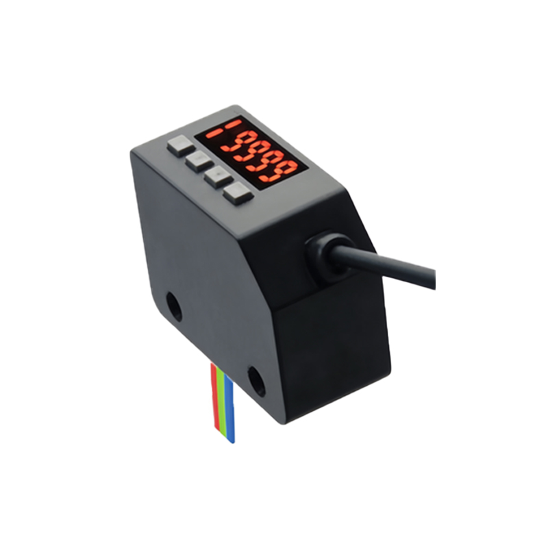
Premature failure often stems from incorrect sensor selection. Engineers must meticulously match the sensor to the operational environment. Key selection criteria include sensing range, response time, light source type, and housing material. For harsh environments, sensors with robust IP (Ingress Protection) ratings (e.g., IP67, IP69K) are essential to resist dust, water, and chemical washdowns. Consider the target object's properties: color, material, surface finish, and size. A shiny object might cause issues with a diffuse sensor, while a transparent object may require a polarized retro-reflective model. Choosing a sensor with a generous excess gain margin for the application provides a buffer against lens contamination and component aging, directly contributing to an extended operational life.
Implementing Optimal Installation Practices
Proper installation is critical for reliable, long-term performance. Ensure precise alignment for through-beam and retro-reflective types; even minor misalignment can weaken the signal. Mount sensors securely using vibration-resistant brackets to prevent loosening over time. Avoid mounting in locations subject to mechanical impact from passing objects. For diffuse sensors, maintain the recommended sensing distance and angle relative to the target. It is crucial to prevent optical crosstalk—interference from adjacent sensors—by maintaining adequate spacing or using models with modulated light and synchronous detection. Providing stable, clean power within the sensor's specified voltage range prevents electrical stress on internal components.
Proactive Environmental Protection and Maintenance
The operating environment is the primary adversary of sensor longevity. Dust, oil, steam, and condensation can coat the lens, attenuating the light signal. Implementing physical protection, such as transparent protective shields or air curtains (air knives), can keep lenses clean in dirty environments. In applications with significant temperature fluctuations, select sensors with wide operating temperature ranges and consider thermal shielding to prevent internal condensation. Establishing a routine preventive maintenance schedule is non-negotiable. This includes regular visual inspection of the lens for contamination and cleaning with appropriate, non-abrasive materials. Periodically verify the sensor's alignment and signal strength to catch degradation before it causes a system fault.
Managing Electrical and Load Considerations
Electrical factors are a common but overlooked cause of sensor degradation. Always use correctly rated power supplies and ensure proper grounding to mitigate electrical noise and voltage spikes, which can damage sensitive circuitry. For sensors driving inductive loads (like relays or solenoids), employ protective circuits such as flyback diodes or surge suppressors to absorb voltage transients generated when the load de-energizes. Adhere strictly to the sensor's maximum load ratings; consistently operating at the limit generates excess heat and stresses output transistors. Utilizing intermediate relays for heavy loads can isolate the sensor from direct switching stress, thereby preserving its switching components.
Leveraging Advanced Features for Enhanced Durability
Modern photoelectric sensors offer built-in features designed to enhance reliability and lifespan. Functions like automatic sensitivity adjustment (teaching or background suppression) allow the sensor to adapt to gradual environmental changes like lens dirt accumulation. Sensors with IO-Link or other diagnostic communication protocols enable predictive maintenance by providing real-time data on parameters like operating temperature, signal strength, and internal health. This allows for maintenance to be performed based on actual condition rather than a fixed schedule. Additionally, choosing models with robust housing materials like stainless steel or high-grade plastics (PBT, PVDF) for specific chemical exposures can prevent housing degradation and seal failure.
Troubleshooting and End-of-Life Planning
Despite best practices, sensors will eventually require attention. A systematic troubleshooting approach—checking power, alignment, lens cleanliness, and load—resolves most issues. Monitoring the stability of the received signal strength (often indicated by an LED on the sensor) is a powerful diagnostic tool. A declining signal indicates contamination or misalignment. Understand the typical failure modes, such as LED output decay over tens of thousands of hours or output circuit failure. For critical applications, plan for a proactive replacement schedule based on the sensor's documented MTBF (Mean Time Between Failures) and the criticality of the process it controls, ensuring system uptime and avoiding unplanned downtime.