Understanding Proximity Switch Sensors in Sliding Door Systems
Proximity switch sensors are fundamental components in modern automated sliding door systems. These non-contact sensors detect the presence or absence of an object, typically a door panel, within a specified range without any physical contact. The core principle involves generating an electromagnetic field or beam; when a metallic target (the door) interrupts or enters this field, the sensor triggers a state change in its output signal. This signal is then processed by the door's control unit to command the drive mechanism to open or stop. The reliability of the entire door operation hinges on the precise and consistent performance of these sensors. In industrial, commercial, and high-traffic residential settings, selecting the correct sensor type and understanding its installation parameters are critical for safety, energy efficiency, and long-term operational integrity.
Key Types and Their Visual Identification in Images
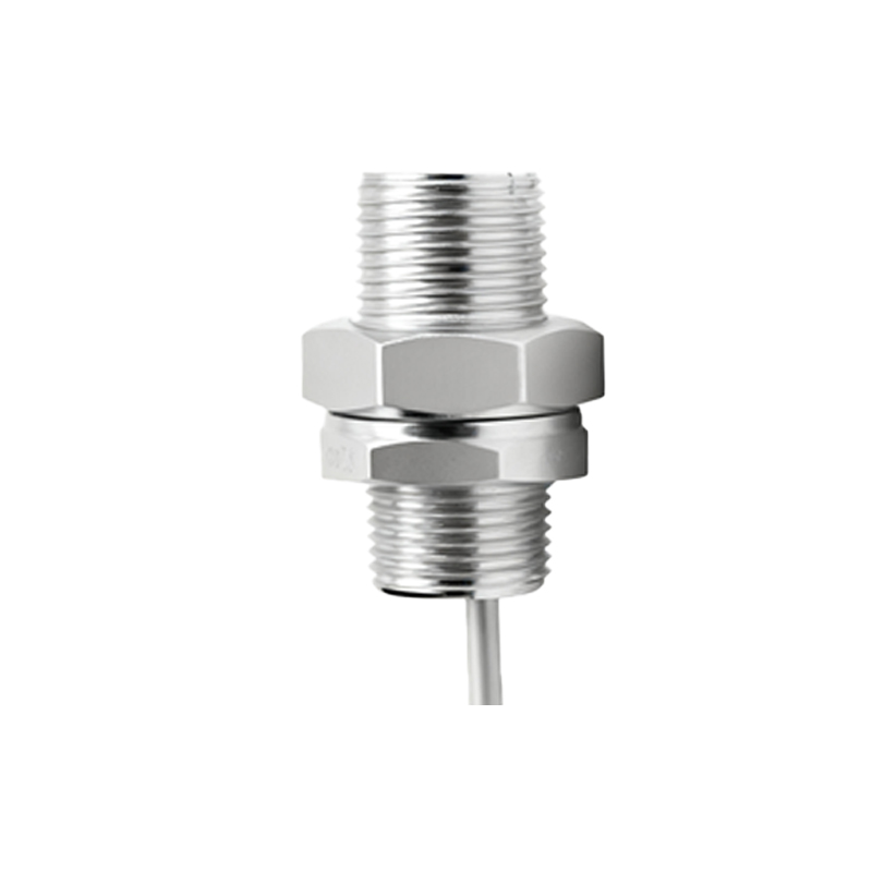
Technical images of proximity sensors for sliding doors reveal distinct physical and operational characteristics. The most common types are inductive and magnetic proximity sensors. Inductive sensors, identifiable in photos by their cylindrical or rectangular metallic housing, are used to detect metallic door components. High-resolution images often show a sensing face from which the oscillating electromagnetic field emanates. Magnetic sensors, or reed switches, are typically smaller and involve two parts: a magnet mounted on the moving door and a switch assembly on the frame. Photographs of these setups clearly show the alignment requirement between the magnet and the switch. Optical sensors, though less common for the main door detection, are sometimes used as safety beams; their images feature a lens for emitting and receiving infrared light. Analyzing product images helps engineers identify form factor, connection types (e.g., M8 or M12 connectors), and IP ratings for environmental protection.
Analyzing Installation and Alignment from Technical Photos
A proper installation image is a tutorial in itself. It demonstrates the critical alignment between the sensor and its target. For inductive sensors, the gap between the sensor face and the metal target is paramount. Technical diagrams and installation photos usually specify this nominal sensing distance (Sn), which is often a few millimeters. Images show sensors mounted on brackets adjacent to the door track, ensuring the door edge passes within this precise range. Misalignment, visible in poorly executed installations, leads to intermittent operation or failure. Photos also illustrate wiring practices; shielded cables are often used to prevent electromagnetic interference from nearby motors or frequency drives, which could cause false triggering. Close-up images highlight the importance of secure mounting to prevent vibration-induced positional drift over time.
Interpreting Sensor Output Signals via Diagrams
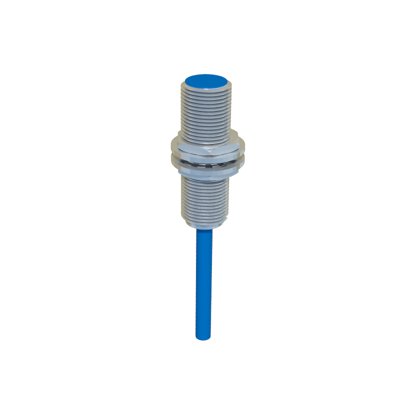
Beyond physical appearance, technical documentation includes waveform diagrams and timing charts that are essential for troubleshooting. These images depict the sensor's output signal in relation to the target's position. A common diagram shows a Normally Open (NO) configuration: the output voltage switches from low to high (or vice-versa, depending on PNP/NPN design) when the door enters the sensing range. Timing diagrams are crucial for systems with multiple sensors, such as a primary open/close sensor and a separate safety-edge sensor. They show the sequence and duration of signals required for a safe opening cycle. Understanding these graphical representations allows maintenance personnel to use an oscilloscope or multimeter to verify sensor health, diagnosing issues like slow switching times or signal dropouts that are not apparent from a static physical inspection.
Common Failure Modes Visible in Inspection Images
Forensic analysis of images from failed installations provides valuable lessons. Common visual cues of sensor failure include physical damage to the housing or sensing face from impact, visible corrosion on connectors or housings in humid environments (indicating an insufficient IP rating), and melted or discolored plastic from excessive ambient heat. Thermal imaging pictures can reveal abnormal heat generation in a sensor due to internal short circuits or excessive load current. Another frequent issue, visible upon close inspection, is the accumulation of metallic dust or debris on an inductive sensor's face, which can dampen the electromagnetic field and reduce the effective sensing range. Comparative images of a clean versus contaminated sensor are powerful tools for preventative maintenance training.
Selecting the Right Sensor Based on Technical Imagery
When reviewing product catalogs or datasheets, engineers must synthesize information from both specifications and images. A high-quality technical photograph should allow assessment of build quality, such as the robustness of the housing and the quality of cable strain relief. Cross-sectional cutaway images reveal internal construction, showing the coil arrangement in an inductive sensor or the reed capsule in a magnetic sensor, which speaks to its sensitivity and durability. Images showing the sensor in context—installed on a specific door profile or within a control cabinet—aid in spatial planning and compatibility verification. The trend towards IO