Introduction to Inductive Proximity Sensing
Inductive proximity sensors are fundamental components in industrial automation, providing non-contact detection of metallic objects. The TMF18-08 model represents a specific implementation within this category, designed for reliable operation in demanding environments. These sensors operate on the principle of electromagnetic induction. An internal oscillator generates a high-frequency electromagnetic field that radiates from the sensor's active face. When a conductive metal target enters this field, eddy currents are induced on the target's surface. This causes a change in the oscillation amplitude within the sensor, which is detected by a threshold circuit, triggering a solid-state output switch. This technology is prized for its robustness, as it has no moving parts and is largely immune to dust, oil, and other non-metallic contaminants.
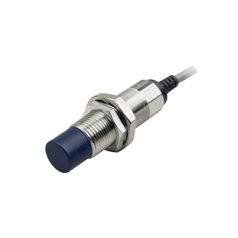
Key Specifications of the TMF18-08 Sensor
The TMF18-08 is typically an 18mm diameter cylindrical sensor with an 8mm nominal sensing distance (Sn). This sensing range is calibrated for a standard mild steel target. It's crucial to note that the effective sensing distance can vary with different metals; for instance, it reduces for stainless steel and is further reduced for non-ferrous metals like aluminum or copper due to differences in electrical conductivity and permeability. The sensor usually features a built-in LED status indicator for operational diagnostics. Common output configurations include NPN (sinking) or PNP (sourcing) transistor outputs, in both normally open (NO) and normally closed (NC) logic variants, allowing for flexible integration into various control systems, including PLCs. The housing is often constructed from nickel-plated brass or stainless steel, offering high resistance to mechanical impact and industrial chemicals.
Electrical Characteristics and Wiring
Operating voltage for DC models typically ranges from 10-30V DC, ensuring compatibility with standard industrial control voltages. The sensor consumes a low quiescent current and provides a rated switching current, for example, up to 200mA, which is sufficient to directly drive relays, solenoid valves, or PLC input modules. Proper wiring is essential: the brown wire is connected to the positive supply voltage (+V), the blue wire to the negative or common (0V), and the black wire is the switched output signal. For models with a wire break or short-circuit protection feature, the sensor will enter a safe state without damaging the internal circuitry. Shielding and proper grounding are recommended in electrically noisy environments to prevent false triggering.
Installation and Mounting Considerations
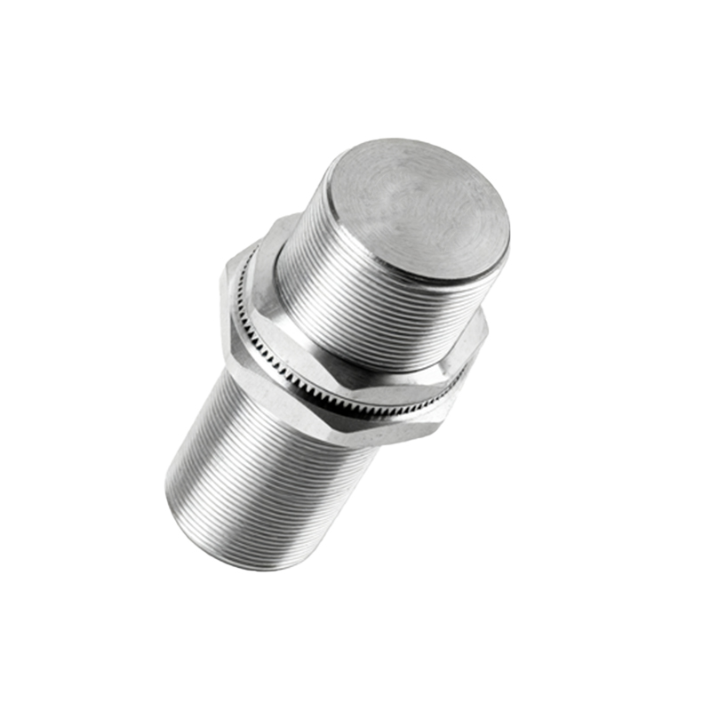
Correct installation is critical for optimal performance. The TMF18-08 can be mounted by its threaded barrel (commonly M18x1) into a matching nut or fixture. Flush-mountable designs allow installation in metal brackets without a lateral clearance requirement, whereas non-flush models require a specific free zone around the sensing face to avoid interference from the surrounding metal. The target approach should be axial to the sensor face for the stated sensing distance. Lateral or skewed approaches can reduce the effective range. Environmental factors such as extreme temperatures, strong alternating magnetic fields, or welding currents can affect performance, so the sensor's IP rating (e.g., IP67) should be verified to ensure it matches the application's ingress protection needs.
Application Scenarios in Industrial Automation
The TMF18-08 finds extensive use across numerous sectors. In automotive assembly lines, it detects the presence of metal components like pistons or gears. In packaging machinery, it counts metal cans or verifies the position of a metallic actuator. On conveyor systems, it serves as an end-of-travel limit switch for metallic trolleys or as a part detection sensor for sorting. In metalworking and CNC machinery, it provides precise position feedback for tool changers or workpiece clamping verification. Its reliability makes it suitable for safety-interlock systems where detecting the closed position of a metal guard door is necessary to enable machine operation.
Troubleshooting and Maintenance Practices
Despite their durability, sensors can encounter issues. Common problems include failure to detect, constant activation, or shortened sensing range. Initial checks should always involve the power supply voltage and current load. The status LED is a primary diagnostic tool: a steady light may indicate a target in range, a blinking light could signal an overload or wiring fault. Ensuring the target material, size, and approach speed are within specifications is vital. Accumulation of metallic swarf or dust directly on the sensing face can cause permanent activation and should be cleaned regularly. For persistent electrical issues, verifying the output type (NPN/PNP) matches the controller's input circuit is a necessary step.
Comparison with Other Sensor Technologies
While inductive sensors like the TMF18