Introduction to Proximity Sensor Fundamentals
Proximity sensors are pivotal components in modern industrial automation, designed to detect the presence or absence of an object within a specified range without physical contact. Their operation hinges on various physical principles, primarily electromagnetic, capacitive, and inductive. The schematic diagram of a proximity sensor is the blueprint that details its electronic architecture, illustrating how components interact to achieve non-contact detection. Understanding this schematic is crucial for engineers involved in system design, troubleshooting, and integration. A typical schematic reveals the sensor's core: an oscillator circuit, a signal conditioning unit, a detection circuit, and an output stage. Each block plays a specific role in converting a physical phenomenon into a reliable electrical signal. This guide delves into the common schematic configurations, breaking down the circuitry to provide a clear, technical comprehension of their operation.
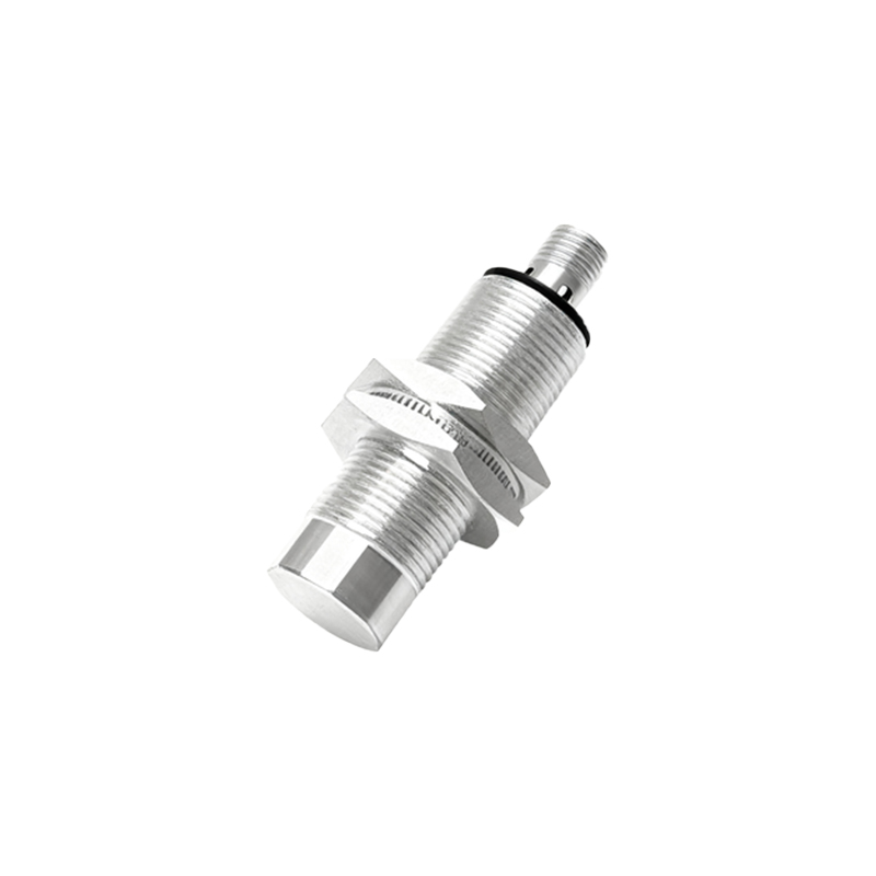
Core Components in a Typical Schematic
Examining a standard inductive proximity sensor schematic, several key components emerge. The heart is the LC oscillator, comprising an inductor (the sensing coil) and a capacitor. This circuit generates a high-frequency electromagnetic field from the sensor's face. When a metallic target enters this field, eddy currents are induced, causing a change in the oscillator's amplitude or frequency. This change is monitored by a subsequent detection circuit, often a Schmitt trigger or a comparator. The detection circuit's output then drives the final output stage, which is typically an NPN or PNP transistor configured as a switch. The schematic also includes protection elements like reverse polarity diodes, voltage regulators, and sometimes short-circuit protection circuits. Power supply filtering capacitors and resistors for biasing the active components are also clearly depicted, ensuring stable operation in electrically noisy industrial environments.
Analyzing the Oscillator and Detection Circuit

The oscillator section in the schematic is critical. It usually shows a transistor or an integrated circuit configured as a Colpitts or Hartley oscillator, connected to the resonant LC tank. The values of the inductor and capacitor determine the operating frequency, often in the range of 100 kHz to 1 MHz. The schematic will show how the oscillation signal is tapped and fed into the detection circuit. The detection circuit, often symbolized by a comparator IC, compares the oscillator's signal level against a preset reference voltage. In the absence of a target, the oscillation amplitude is high. When a target dampens the oscillation, the amplitude drops below the threshold, causing the comparator's output state to change. This digital transition is the primary detection event. The schematic details the feedback paths and hysteresis resistors that prevent output chattering when the target is at the precise detection boundary.
Output Stage Configuration and Wiring
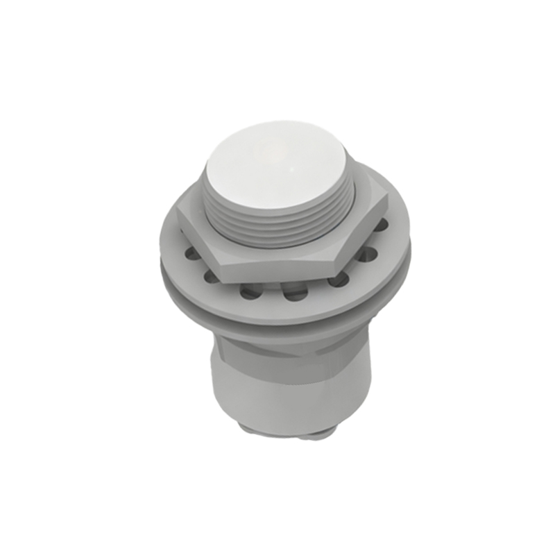
The output stage is clearly defined in the schematic, showing the connection of the output transistor (sinking-NPN or sourcing-PNP). For a 3-wire DC sensor, the schematic labels the wires: brown for V+, blue for common (0V), and black for the switched output. It illustrates how the load (e.g., a PLC input or relay coil) is connected between the output wire and either V+ (for NPN) or common (for PNP). The schematic includes the free-wheeling diode for inductive load protection. For analog output sensors, the schematic replaces the switching transistor with an operational amplifier circuit that provides a current (4-20mA) or voltage (0-10V) signal proportional to the target distance. This section of the diagram is vital for correct electrical integration and preventing damage from incorrect wiring.
Capacitive and Ultrasonic Sensor Schematic Variations
While inductive sensors are common for metals, capacitive and ultrasonic sensors have distinct schematics. A capacitive proximity sensor schematic features an RC oscillator where the sensing electrode forms one plate of a capacitor. The target alters the dielectric constant, changing the capacitance and thus the oscillation frequency. The detection circuit is tuned to this frequency shift. The schematic shows the guard ring driver circuit, which is essential for focusing the field and preventing false triggers from moisture or contaminants. An ultrasonic sensor schematic, used for distance measurement, is more complex. It depicts a transmitter circuit with a piezoelectric transducer driven by a burst generator and a separate, highly sensitive receiver amplifier chain. A microcontroller or timing IC is shown to calculate the time-of-flight of the sound pulse. These variations highlight how the core principle of oscillation and detection is adapted to different physical sensing modalities.
Practical Considerations for Design and Troubleshooting
For an engineer, the schematic is a troubleshooting map. Common issues like insufficient sensing range often point to problems in the oscillator's LC tank or power supply stability, visible as incorrect voltage levels at test points on the diagram. False triggering can often be traced to inadequate shielding or noise immunity, indicated by missing filter components in the signal path. When modifying or