Understanding the Basics of Proximity Sensor Wiring
Proximity sensor wiring diagrams are essential blueprints for installation and troubleshooting in industrial automation. These diagrams, often provided by manufacturers, detail electrical connections, pin configurations, and operational parameters. To read them effectively, start by identifying key components: power supply terminals, output signals, and grounding points. Most diagrams use standardized symbols, such as squares for sensors and lines for wires, with labels indicating voltage levels (e.g., 10-30V DC) and current ratings. Familiarize yourself with common abbreviations like "PNP" (positive switching) or "NPN" (negative switching), which define output types. Always refer to the sensor's datasheet for specific details, as variations exist between models.
Decoding Symbols and Notations in Diagrams
Wiring diagrams employ a visual language of symbols and notations to convey information efficiently. Look for icons representing the sensor body, typically shown as a rectangle or circle with labeled pins. Numbers or letters next to pins correspond to functions: for instance, "1" might indicate power supply (+V), "2" for output signal, and "3" for ground (-V). Color codes may be included, with brown often for positive voltage and blue for negative. Notations like "NO" (normally open) or "NC" (normally closed) describe output states. Pay attention to arrows or dashed lines, which can indicate sensing direction or shielded cables. Cross-referencing these elements with the legend ensures accurate interpretation.
Step-by-Step Guide to Interpreting Connections
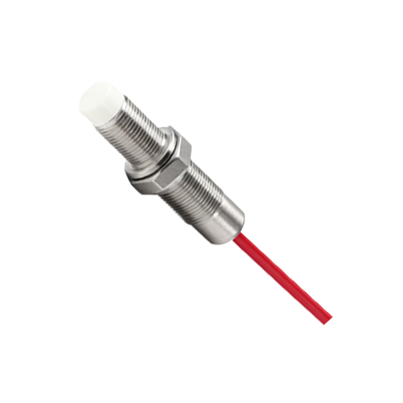
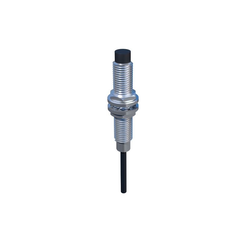
Begin by locating the sensor's input section on the diagram, which outlines power requirements. Connect the positive lead from the power source to the designated "+V" pin and the negative to "-V". Next, identify the output section: for a PNP sensor, the output pin switches positive voltage to the load (e.g., a PLC input), while an NPN sensor switches negative. Diagrams often show load devices, such as relays or controllers, with connections marked. Check for additional features like short-circuit protection or diagnostic LEDs, indicated by extra symbols. Verify wire gauges and insulation types if specified, as they impact safety and performance. Always double-check against real-world sensor markings to avoid errors.
Common Pitfalls and Troubleshooting Tips
Misreading diagrams can lead to issues like incorrect polarity, which may damage sensors or equipment. Avoid confusing PNP and NPN wiring; mixing them can cause output failures. Ensure proper grounding to prevent noise interference, especially in environments with motors or high-frequency devices. If the sensor doesn't activate, review the diagram for enable pins or timing sequences. Use a multimeter to test voltages at each pin against the diagram's specifications. For complex systems, isolate sections and trace connections methodically. Consult manufacturer guidelines for error codes or LED indicators shown in diagrams, as they aid in diagnosing faults like overloads or misalignment.
Practical Applications and Best Practices
In real-world scenarios, such as conveyor systems or robotic arms, wiring diagrams guide integration with other components. Implement best practices by labeling wires according to diagram codes and using shielded cables for long runs to reduce EMI. Regularly update diagrams to reflect modifications, ensuring documentation aligns with actual setups. Train personnel on diagram literacy to enhance maintenance efficiency. For advanced sensors with IO-Link or analog outputs, diagrams may include communication protocols—refer to supplementary manuals for details. Ultimately, mastering diagram reading minimizes downtime and optimizes sensor performance in diverse industrial applications.