Introduction to Photoelectric Sensors
Photoelectric sensors are essential components in industrial automation, widely used for object detection, positioning, and counting. These devices operate by emitting a light beam and detecting changes in the received light intensity, which occur when an object interrupts or reflects the beam. The core principle relies on the interaction between light and matter, enabling non-contact sensing with high precision and reliability. Photoelectric sensors are favored in various industries due to their versatility, fast response times, and ability to function in harsh environments. This article delves into the structural components and schematic diagrams of photoelectric sensors, providing a detailed overview for engineers and technicians in the electrical field.
Basic Structural Components
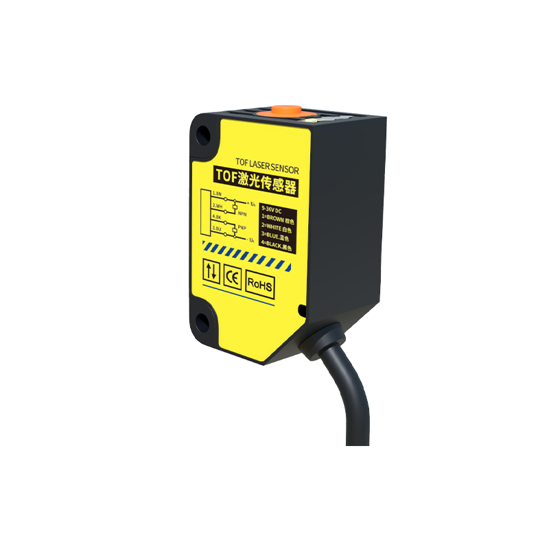
The structure of a photoelectric sensor typically consists of three main parts: the emitter, receiver, and control circuitry. The emitter is a light source, often an LED (Light Emitting Diode) or laser diode, which generates a focused beam of light. Common light types include visible red, infrared, or laser light, chosen based on application requirements such as range and environmental conditions. The receiver, usually a phototransistor or photodiode, detects the light beam and converts it into an electrical signal. The control circuitry processes this signal to determine the presence or absence of an object, triggering outputs like switching actions. Additional elements may include lenses for beam focusing, housings for protection against dust and moisture, and connectors for integration into larger systems. Understanding these components is crucial for selecting and maintaining sensors in industrial setups.
Working Principles and Modes
Photoelectric sensors operate in several modes, each suited to specific applications. The through-beam mode involves separate emitter and receiver units placed opposite each other; an object is detected when it blocks the light beam, offering long-range and high-accuracy detection. In the retro-reflective mode, the emitter and receiver are housed together, and a reflector bounces the light back; detection occurs when the beam is interrupted, ideal for medium-range tasks. The diffuse reflective mode combines emitter and receiver in one unit, relying on light reflection from the object itself, suitable for short-range detection where reflectivity varies. Advanced sensors may incorporate background suppression or fiber optic elements for enhanced performance. The schematic diagrams for each mode illustrate the light path and signal flow, aiding in troubleshooting and design optimization.
Schematic Diagram Analysis
A schematic diagram of a photoelectric sensor provides a visual representation of its electrical and optical connections. Typically, it includes symbols for the emitter (e.g., an LED symbol), receiver (e.g., a phototransistor symbol), and associated components like resistors, capacitors, and integrated circuits. The diagram shows how the emitter is driven by a current source, often regulated to ensure stable light output, while the receiver circuit amplifies and processes the detected signal. Output stages may feature transistors or relays for switching loads. Key aspects to note in schematics are power supply requirements, signal conditioning paths, and protection mechanisms against overload or interference. By studying these diagrams, engineers can diagnose faults, customize sensors, or integrate them into control systems like PLCs (Programmable Logic Controllers).
Applications and Industry Use Cases
Photoelectric sensors are integral to numerous industrial applications, enhancing efficiency and safety. In manufacturing, they are used for conveyor belt monitoring, detecting products for packaging or sorting. Automotive industries employ them for part alignment and robotic guidance, while in logistics, they facilitate inventory management through barcode scanning. Environmental factors like dust, fog, or varying light conditions can affect performance, so selecting the right sensor type—such as polarized models for shiny surfaces—is vital. Regular maintenance, including lens cleaning and alignment checks, ensures longevity. Emerging trends include smart sensors with IoT connectivity for real-time data analytics. Understanding structure and schematics helps in adapting these sensors to evolving technological demands.
Conclusion and Best Practices
In summary, photoelectric sensors rely on a well-defined structure and precise schematic design to achieve reliable object detection. Key takeaways include the importance of choosing appropriate modes (through-beam, retro-reflective, or diffuse) based on range and environmental needs, and interpreting schematic diagrams for effective implementation. Engineers should prioritize factors like response time, sensing distance, and environmental ratings when selecting sensors. Regular calibration and adherence to manufacturer guidelines can prevent downtime. As automation advances, photoelectric sensors will continue to evolve, offering greater integration with digital systems. By mastering their fundamentals, professionals can leverage these devices to optimize industrial processes and drive innovation in the electrical engineering field.