Understanding the 3-Wire Photoelectric Sensor
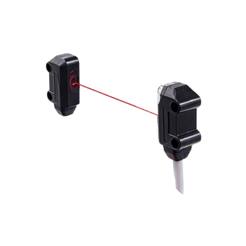
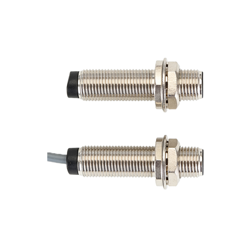
A 3-wire photoelectric sensor is a fundamental component in industrial automation, offering a reliable solution for object detection, counting, and positioning. Unlike 2-wire sensors that are wired in series with the load, 3-wire sensors provide separate paths for power supply and the output signal. This design offers distinct advantages, including lower leakage current, compatibility with a wider range of controllers (PLCs, relays), and the ability to source or sink current. The three wires are universally color-coded: brown for the positive supply voltage (typically +12 to +24 VDC), blue for the common negative or 0V, and black (or sometimes white) for the output signal. Understanding this basic configuration is the critical first step before any connection is made.
Essential Pre-Wiring Safety and Preparations
Prior to any electrical work, safety is paramount. Always disconnect and lock out all power sources to the control panel or machine. Verify the voltage is off using a multimeter. Carefully review the sensor's datasheet to confirm its specifications: operating voltage range, output type (NPN or PNP), and current rating. Gather the necessary tools: wire strippers, crimping tools, appropriate ferrules, screwdrivers, and your wiring diagram. Ensure you have the correct gauge of wire for the expected current and distance. Planning the wire routing away from high-voltage cables and moving parts to prevent interference or damage is a crucial preparatory step often overlooked.
Identifying Output Configuration: NPN vs. PNP
This is the most critical conceptual step. The black (output) wire's behavior depends entirely on whether the sensor has an NPN or PNP transistor output. An NPN sensor, also known as a sinking sensor, switches the negative or 0V line to the load. When active, the black wire connects internally to the blue wire (0V). A PNP sensor, or a sourcing sensor, switches the positive voltage line. When active, its black wire connects internally to the brown wire (+V). The load (e.g., a PLC input) must be connected to complete the circuit accordingly. Misidentifying this will result in the sensor not functioning. The sensor housing or datasheet will clearly state "NPN" or "PNP."
Wiring a 3-Wire NPN Photoelectric Sensor
For a standard NPN sensor, follow this procedure. First, connect the brown wire to the positive terminal of your DC power supply (e.g., +24VDC). Second, connect the blue wire to the negative or 0V terminal of the same power supply. The black output wire is connected to one side of your load (e.g., terminal X0 on a PLC input module). The other side of that PLC input must then be connected to the positive supply voltage (+24VDC). This creates a circuit where the sensor, when activated, "sinks" the current from the PLC input down to 0V, completing the path and signaling the PLC. Always double-check that the PLC input card is configured for a sinking (NPN) signal.
Wiring a 3-Wire PNP Photoelectric Sensor
The wiring for a PNP sensor mirrors that of the NPN but with a key difference in the load connection. Again, connect brown to +V and blue to 0V. The black output wire is connected to one side of your load (PLC input X0). However, the other side of that PLC input must now be connected to the 0V or common negative of the power supply. In this configuration, the active PNP sensor "sources" positive voltage to the PLC input. The current flows from the sensor, through the load, and back to the supply's negative. Ensure the connected PLC input is compatible with a sourcing (PNP) signal.
Connecting to a PLC Digital Input Module
Modern PLCs are the most common load for these sensors. Most PLC input modules have a common terminal for a group of inputs. For an NPN sensor setup, this common terminal is typically jumpered to the positive voltage (+V). Each input point then receives the switched 0V from the sensor's black wire. For a PNP setup, the common terminal is jumpered to 0V, and each input receives the switched +V from the sensor. Refer to your PLC hardware manual for the exact terminal designations and jumper settings. Incorrect common terminal wiring is a frequent cause of non-operation.
Verification, Testing, and Troubleshooting
After connections are secure and before restoring main power, visually inspect all terminations for loose strands or potential shorts. Apply power and observe the sensor's indicator LED. Most sensors have a power LED and a separate output status LED. Trigger the sensor by placing an object within its detection range. The output LED should illuminate. Use a multimeter to measure the voltage between the black wire and blue wire. For an inactive PNP sensor, you should read near 0V; when active, you should read the supply voltage (+24V). For an inactive NPN sensor, you may read a floating voltage; when active, you should read near 0V. If the sensor fails to operate, re-check the power, ground, output type, and load connections systematically.