Introduction to Photoelectric Sensor Fundamentals
Photoelectric sensors are indispensable components in modern industrial automation, utilizing light beams to detect the presence, absence, or distance of objects. Their operation is based on the principle of converting light signals into electrical signals. The core components typically include an emitter (light source such as LED or laser diode), a receiver (phototransistor, photodiode, or photo IC), and associated signal processing circuitry. These sensors are broadly categorized into three main types: through-beam (opposed), retro-reflective, and diffuse (proximity) sensors, each suited for specific application scenarios based on required sensing distance, environmental conditions, and object characteristics. The choice of light source wavelength—visible red, infrared, or laser—further tailors the sensor to challenges like background suppression or color detection. Understanding these fundamentals is crucial for designing effective application circuits.
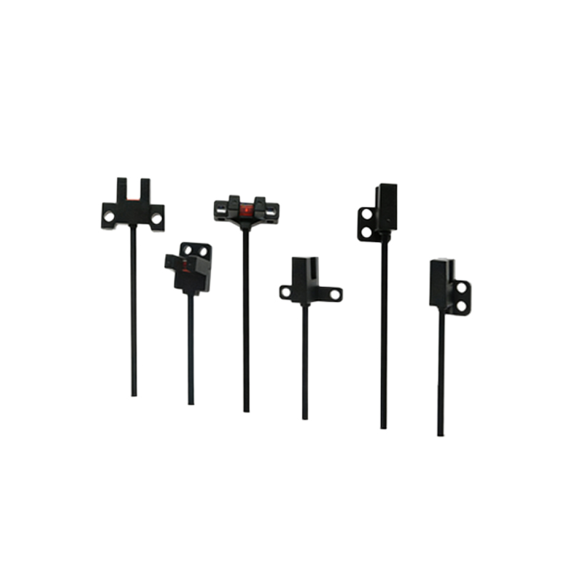
Core Circuit Design for Through-Beam Sensors
Through-beam sensors offer the longest sensing ranges and highest reliability, as the emitter and receiver are separate units. A practical emitter circuit often involves driving an infrared LED with a constant current source to ensure stable light intensity, immune to voltage fluctuations. A simple circuit can use a transistor (e.g., 2N2222) in a common-emitter configuration, with a series resistor to set the current, often pulsed to increase LED lifespan and reduce power consumption. The receiver circuit is critical. A phototransistor is commonly used in a switch mode. It can be connected in a voltage divider configuration with a pull-up resistor at the collector. The output voltage at the collector drops when light is received (transistor conducts). This analog signal is then fed into a comparator circuit (using an IC like LM393) to create a clean, digital ON/OFF signal. Hysteresis via positive feedback is essential to prevent output oscillation when the detected light is at the threshold level, ensuring a stable output in noisy industrial environments.
Designing Retro-Reflective and Diffuse Sensor Circuits
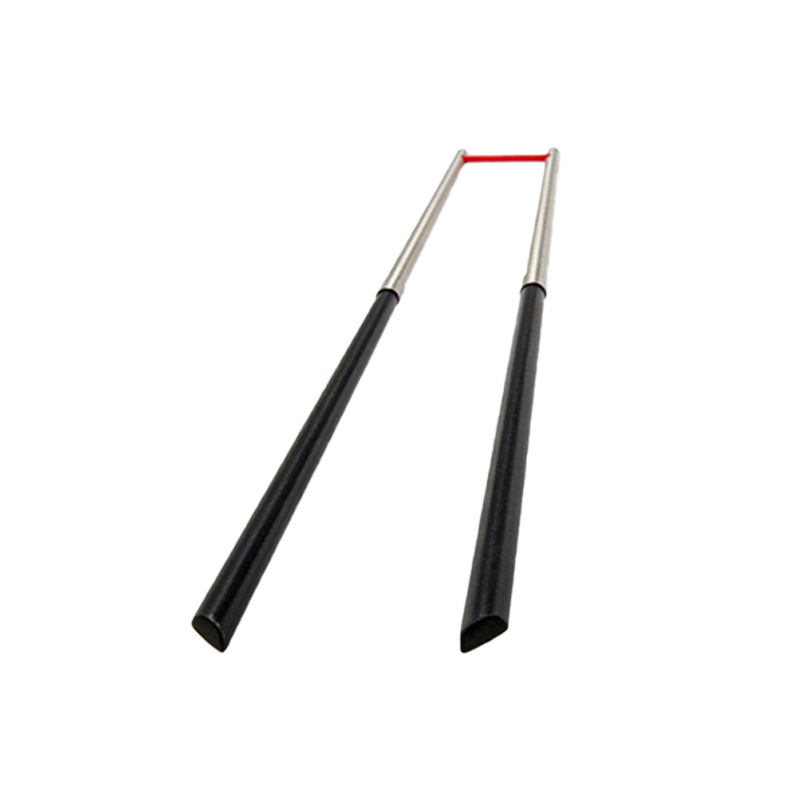
Retro-reflective sensors, where emitter and receiver are housed together, use a reflector. Their circuit is similar to through-beam but must incorporate modulation and synchronous detection to ignore ambient light and detect only the modulated beam reflected from the target. This involves pulsing the LED at a specific frequency (e.g., 5-10 kHz) and using a tuned amplifier or a PLL (Phase-Locked Loop) circuit in the receiver path to respond only to that frequency. Diffuse (proximity) sensors, which detect light reflected directly from the object, face the challenge of weak signal strength. Here, the receiver circuit requires high gain. Using a photodiode in photovoltaic mode connected to a high-input-impedance operational amplifier (op-amp) in a transimpedance configuration is effective. This circuit converts the photodiode's small current into a usable voltage. Subsequent stages of amplification and filtering are necessary. For both types, careful shielding of the receiver and optical filtering matching the emitter wavelength are vital to minimize interference from ambient light sources like factory lighting.
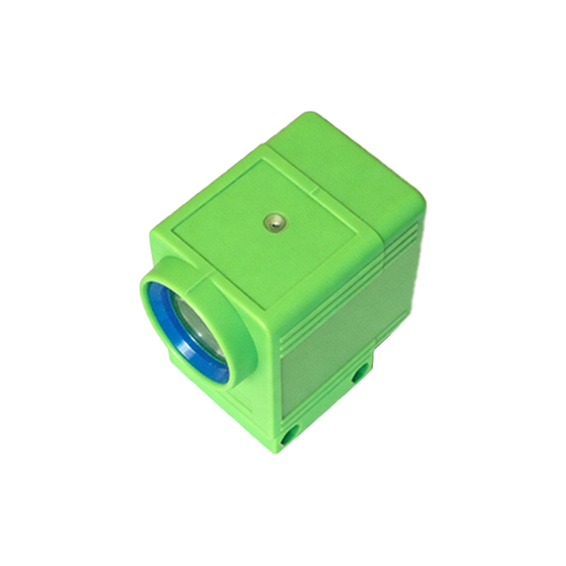
Signal Conditioning and Output Interface Circuits
The raw signal from the photodetector is rarely used directly. Signal conditioning is paramount for reliability. After initial amplification, filtering (low-pass to remove high-frequency noise) is applied. For digital output, a comparator stage, as mentioned, provides a crisp switch signal. The comparator's reference voltage can be made adjustable via a potentiometer to set the sensitivity or detection threshold. For analog output proportional to distance or intensity, such as in analog diffuse sensors, the conditioned voltage can be buffered and scaled using an op-amp. The final output stage must interface with industrial controllers like PLCs (Programmable Logic Controllers). Common output configurations include NPN/PNP transistor open-collector outputs, which are simple and robust for switching loads. For longer cable runs or noisy environments, a line driver output (like RS-422) or a current loop output (4-20 mA) provides superior noise immunity. Protection circuits, such as flyback diodes for inductive loads and TVS diodes for voltage spikes, are mandatory in the output stage to ensure longevity.
Practical Considerations and Troubleshooting Tips
Successful implementation extends beyond circuit diagrams. Power supply decoupling with capacitors (e.g., 100nF ceramic and 10µF electrolytic) near the ICs is essential to prevent noise from affecting sensitive analog stages. For sensors in harsh environments, conformal coating can protect the PCB from dust, moisture, and chemicals. Lens selection and cleaning are often overlooked; a dirty lens can drastically reduce performance. When troubleshooting, a systematic approach is key. First, verify power supply levels. Use an oscilloscope to check if the emitter is pulsing correctly. Measure the receiver's output before the comparator to see the analog signal level change when an object is present. If the sensor is unstable, check for electrical noise coupling into signal lines or insufficient hysteresis. For intermittent failures, inspect connectors and cables for damage. Understanding these practical aspects ensures that a well-designed circuit performs reliably on the factory floor for years.