Introduction to 3-Wire Proximity Sensors
In industrial automation and control systems, proximity sensors are indispensable components for non-contact object detection. Among the various configurations, the 3-wire proximity switch sensor is one of the most prevalent and reliable designs. This type of sensor provides a solid-state switching output, eliminating the mechanical wear associated with traditional limit switches. Its three-wire design typically includes connections for power supply, ground, and the output signal, allowing for straightforward integration into programmable logic controller (PLC) systems and other control circuitry. Understanding its internal schematic and operational logic is crucial for proper selection, installation, and troubleshooting in complex electrical panels and machinery.
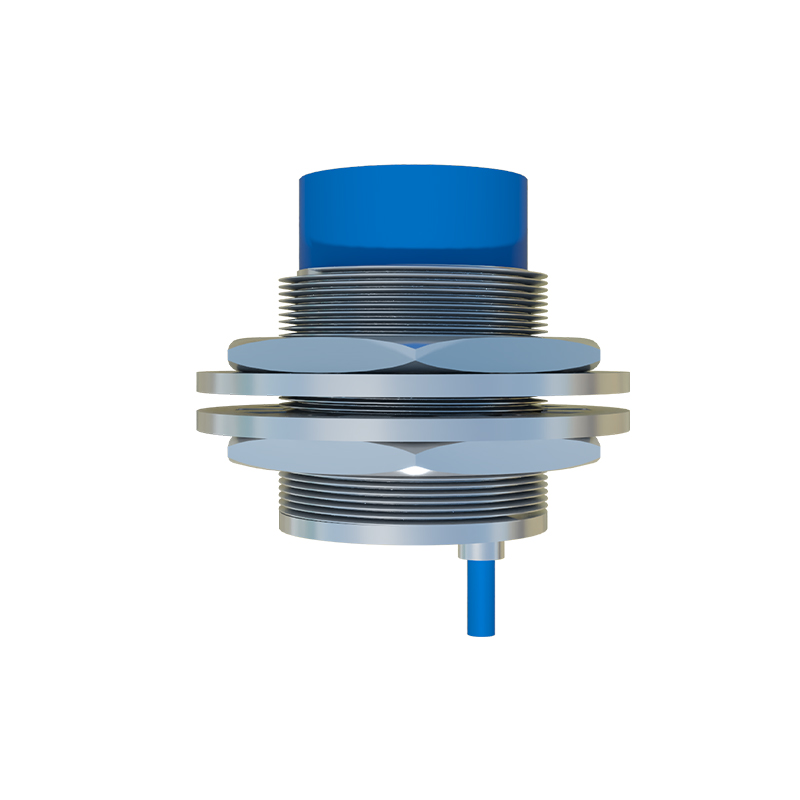
Core Components and Internal Circuitry
The fundamental operation of a 3-wire DC proximity sensor revolves around an oscillator circuit, a detection circuit, and an output switching stage. The oscillator generates a high-frequency electromagnetic field from the sensor's face. When a metallic target (ferrous or non-ferrous, depending on the sensor type) enters this field, eddy currents are induced in the target. This causes a change in the oscillation amplitude, which is detected by the subsequent threshold circuit. This detection signal then triggers the output stage. The output stage commonly uses a transistor—either an NPN (sinking) or PNP (sourcing) type—to act as an electronic switch. This transistor controls the flow of current from the load (e.g., a PLC input, relay coil) to the common or supply rail, thereby providing a clean, bounce-free digital signal.
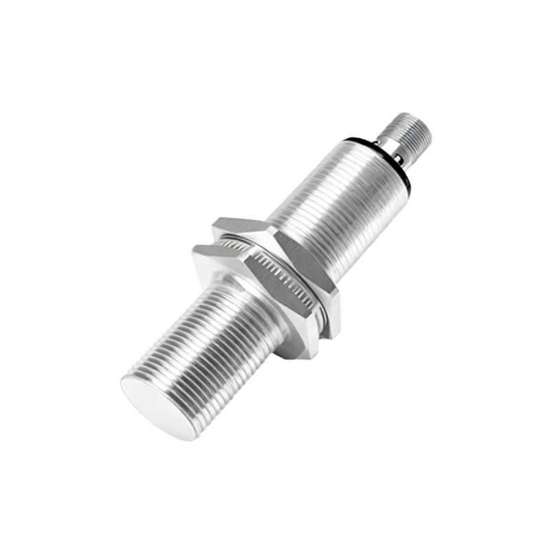
Detailed Analysis of the Working Principle Diagram
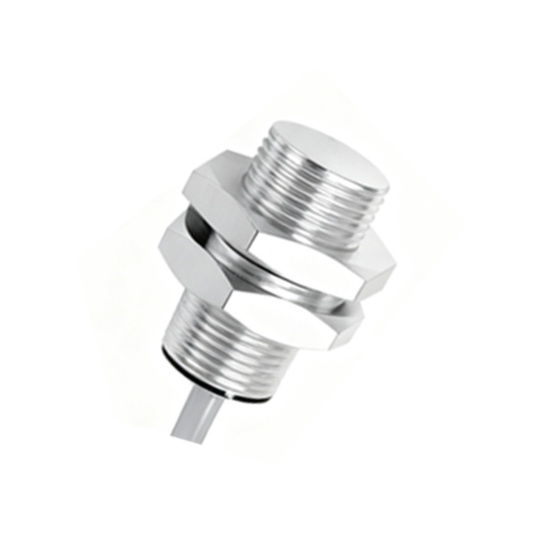
A standard 3-wire DC sensor wiring diagram clearly illustrates the three terminals: Brown wire (+V, typically 10-30V DC), Blue wire (0V or Common), and Black wire (Output). Internally, the brown and blue wires connect to the sensor's power regulation and oscillator circuits. The black output wire is connected to the collector (for NPN) or emitter (for PNP) of the output transistor. The other side of the transistor connects internally to either the blue (0V) or brown (+V) line, defining its sinking or sourcing nature. In an NPN configuration, the transistor switches the load connection to the 0V (Blue) line; when active, it "sinks" current from the load to ground. Conversely, a PNP transistor switches the load to the +V (Brown) line, "sourcing" current from the supply to the load. A protection diode, usually connected across the output transistor, suppresses voltage spikes from inductive loads.
NPN vs. PNP Output Configurations
The choice between NPN and PNP output is fundamental and depends on the control system's input card configuration. An NPN (sinking) sensor, in its active state, connects the output signal line to the negative/common terminal. This is commonly used with PLC input modules that are wired to source current. The PNP (sourcing) sensor, when active, connects the output signal line to the positive supply terminal, suitable for PLC inputs wired to sink current. Mis-matching these configurations will result in the control system failing to detect the sensor's signal. The principle diagram for each type is nearly identical except for the polarity and connection point of the output transistor relative to the load and power rails.
Wiring Practices and Load Connection
Correct wiring is paramount for reliable operation. The power supply (DC) must be connected with correct polarity to the brown (+) and blue (-) wires. The load (e.g., relay coil, PLC digital input) is connected in series with the sensor's output (black wire). For an NPN sensor, one side of the load connects to the positive supply, and the other side connects to the black output wire. When the sensor detects an object, the NPN transistor turns on, completing the circuit from the load, through the transistor, to the blue (0V) wire, thus energizing the load. For a PNP sensor, one side of the load connects to the blue (0V) wire, and the other to the black output wire. Activation allows current to flow from the brown (+V) wire, through the transistor, out the black wire, and through the load to ground.
Key Considerations for Application and Troubleshooting
When applying a 3-wire proximity sensor, engineers must consider several factors beyond the basic diagram. The sensing distance, target material, and environmental conditions (like temperature and presence of contaminants) affect performance. Electrical considerations include ensuring a stable, clean power supply with proper filtering to avoid false triggering. For troubleshooting, a multimeter is essential. Check for the presence