Introduction to Proximity Sensor Power Requirements
Proximity sensors are fundamental components in modern industrial automation, providing non-contact detection of objects. A critical aspect of their integration and reliable operation is their power supply voltage. Unlike simple mechanical switches, these electronic devices require a specific voltage range to function correctly. The operating voltage is not merely a technical specification; it is a key determinant of the sensor's performance, compatibility with control systems, and overall system safety. Selecting the incorrect voltage can lead to sensor failure, erratic operation, or even damage to connected equipment like Programmable Logic Controllers (PLCs). Therefore, a thorough understanding of common voltage standards, their implications, and selection criteria is essential for any engineer or technician working in electrical design, machine building, or maintenance.
Common DC Voltage Standards: 10-30V DC
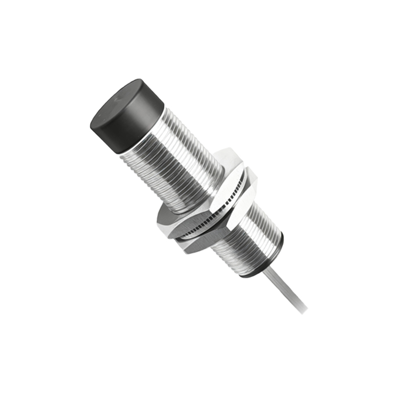
The vast majority of modern proximity sensors operate on Direct Current (DC) power supplies. The most prevalent standard voltage range is 10-30V DC. This wide range offers significant flexibility and robustness in industrial environments. A sensor rated for 10-30V DC can typically function reliably even when the supply voltage experiences fluctuations or drops, which are common in facilities with heavy machinery. Within this range, two nominal voltages are most frequently used: 12V DC and 24V DC. Twenty-four-volt DC systems have become the de facto standard in industrial control panels due to their superior safety characteristics compared to higher voltages and better noise immunity and transmission capabilities compared to lower voltages like 12V DC. Many sensors are designed to be compatible with both, but it is crucial to verify the specific model's data sheet.
The Role of AC Voltage in Proximity Sensors
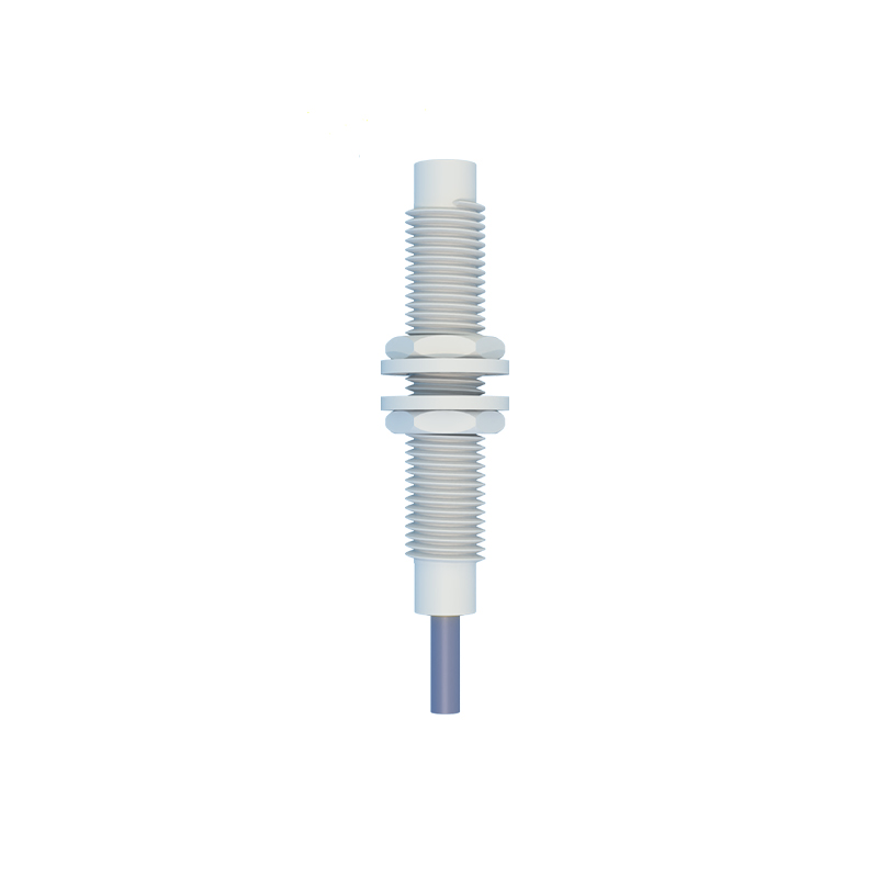
While DC is dominant, Alternating Current (AC) powered proximity sensors are still employed in specific applications. Common AC voltage ratings include 90-250V AC, often aligning with standard mains voltages like 120V AC or 240V AC. These sensors have an internal circuit that rectifies the AC to DC for the sensing element. Their primary advantage is the elimination of a separate DC power supply, allowing direct connection to mains power in some machine tools or older equipment. However, AC sensors generally have a lower switching frequency, may produce more electrical noise, and often have a shorter operational lifespan due to the stress on internal components from the alternating current. Their use is now typically reserved for legacy systems or very specific replacement scenarios.
Two-Wire vs. Three-Wire Sensor Configurations
The wiring configuration of a proximity sensor is intrinsically linked to its voltage supply and connection to the load. Two-wire sensors are connected in series with the load and the power supply. They are simple to wire but have a residual leakage current even when "off," which can sometimes prevent a PLC input from fully turning off. They are commonly available for both AC and DC voltages. Three-wire sensors are the most common type for DC applications. They have separate wires for power supply positive (brown), power supply negative/ground (blue), and the output signal (black). This design provides a clean, solid-state switch output (typically PNP or NPN) with virtually no leakage current, offering superior compatibility with PLCs and other control devices. The voltage rating strictly applies to the brown and blue wires powering the sensor's internal electronics.
Voltage Tolerances and Environmental Considerations
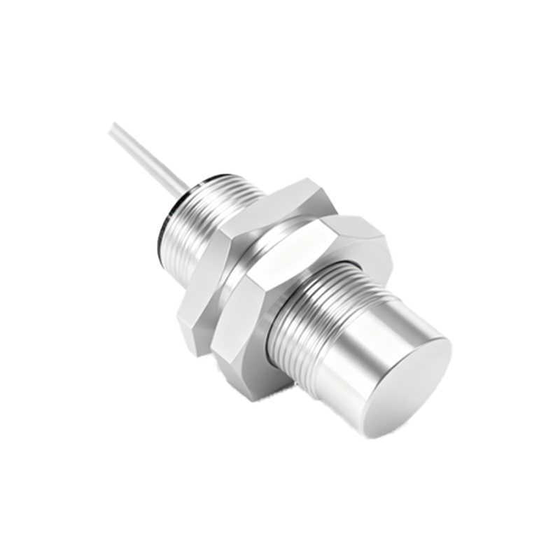
Manufacturers specify not only a nominal voltage but also a permissible operating range. A sensor rated for 10-30V DC should perform reliably anywhere within that span. However, operating at the extreme lower end (e.g., 10.5V) might reduce the sensing distance or output current capability. Conversely, consistently applying voltage at the upper limit can increase internal heat and potentially shorten service life. Environmental factors also interact with voltage. In high-temperature applications, the sensor's internal components may behave differently, and voltage stability becomes even more critical. Long cable runs between the power supply and the sensor can cause a voltage drop due to cable resistance, potentially pulling the voltage at the sensor below its minimum operating threshold. This necessitates proper wire sizing and power supply placement.
Selecting the Correct Voltage for Your Application
The selection process begins with the existing control system architecture. What is the available control voltage in the cabinet or on the machine? For new designs, 24V DC is the recommended starting point for its safety and noise immunity. Next, consider the load. Is the sensor directly driving a relay coil, a pilot light, or a PLC digital input? The sensor's output must be compatible with the load's voltage and current requirements. Always consult the manufacturer's datasheet for the precise operating voltage range, output type, and current ratings.