Introduction to Analog Proximity Sensing Technology
Analog proximity sensors represent a critical class of industrial sensing devices, offering continuous measurement of distance or presence. Unlike their digital counterparts that provide a simple on/off signal, analog sensors output a continuously variable signal, typically a voltage (e.g., 0-10V) or current (e.g., 4-20mA), proportional to the distance of a target object. This capability makes them indispensable in applications requiring precision, such as position control, thickness measurement, and edge guiding. The core operating principle often involves inductive, capacitive, or ultrasonic technologies, with inductive sensors being predominant for detecting metallic objects. The analog output provides a rich data stream, enabling sophisticated control systems to make nuanced adjustments in real-time, thereby enhancing process accuracy and automation flexibility.
Core Operating Principles and Signal Output
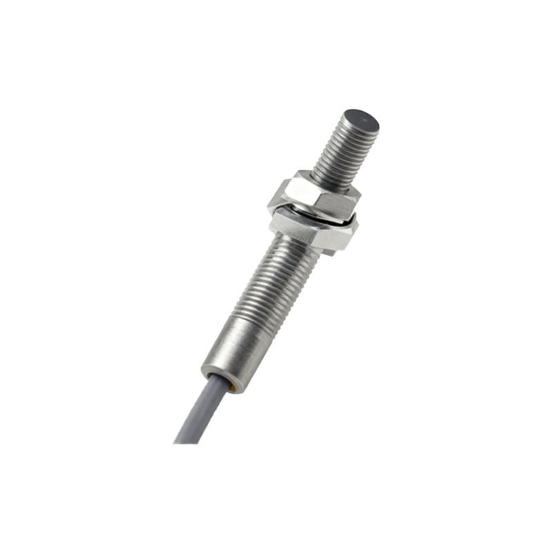
The functionality of an analog proximity sensor hinges on its ability to translate a physical parameter—distance—into a standardized electrical signal. In an inductive analog sensor, an oscillator generates a high-frequency electromagnetic field from its sensing face. When a metallic target enters this field, eddy currents are induced, causing a change in the oscillation amplitude. This change is not merely detected as a threshold but is linearly converted into an analog output. For instance, a sensor with a 10mm sensing range might output 0V when the target is 10mm away and 10V when the target is at 0mm (touching the face). The 4-20mA current loop output is particularly valued in industrial settings for its noise immunity and ability to indicate a wire break (current falls below 4mA). This linear relationship between distance and output is the sensor's most valuable characteristic, though it is typically most linear in the central portion of its nominal range.
Key Selection Criteria for Industrial Applications
Selecting the appropriate analog proximity sensor requires a detailed analysis of the application's demands. The primary factor is the sensing technology: inductive for metals, capacitive for non-metals (plastics, liquids, wood), and ultrasonic for longer ranges or varied materials. The sensing range must be chosen with a safety margin, considering the target material's properties, size, and shape. The output type is another crucial decision; voltage output is common for shorter distances within control cabinets, while current output is preferred for longer cable runs in electrically noisy environments. Environmental factors such as ambient temperature, presence of chemicals, washdown requirements (IP rating), and potential for mechanical shock or vibration must also be rigorously evaluated. Finally, the required linearity, repeatability, and response time will dictate the performance grade and cost of the sensor.
Installation, Calibration, and Alignment Best Practices
Proper installation is paramount to achieving the specified performance of an analog sensor. The sensor must be mounted securely to prevent movement that would introduce measurement error. Alignment relative to the target is critical; for inductive sensors, the target should approach the sensing face perpendicularly. Factors like flank sensitivity (detection from the side) must be considered. Many analog sensors feature teach-in functionality, allowing users to easily set the output range by placing the target at the near and far points of the desired measurement span. Shielding is another vital consideration. Non-shielded (unflush) sensors have a longer range but are susceptible to interference from adjacent metal, while shielded (flush) sensors can be embedded in metal without affecting their operation but offer a shorter sensing distance. Ensuring a stable power supply and correct wiring per the datasheet is fundamental.
Integration with Control Systems and Signal Conditioning
The analog signal from the sensor is the starting point for integration into a broader control system, such as a PLC (Programmable Logic Controller), PAC (Programmable Automation Controller), or industrial PC. The voltage or current signal is connected to an appropriate analog input module. Within the control system, the raw signal value (e.g., 0-27648 counts for a 4-20mA input on a typical PLC) must be scaled to engineering units (e.g., millimeters) using linear transformation functions. Signal conditioning is often necessary to filter out electrical noise, which can be achieved through hardware filters in the input module or software filters (moving average, low-pass) in the control logic. For critical applications, monitoring for signal dropouts or out-of-range values can provide diagnostic information about the process or the sensor itself, enabling predictive maintenance.
Common Applications and Use Case Examples
Analog proximity sensors find utility across a vast spectrum of industries. In automotive manufacturing, they precisely control robot arm position during welding or part placement. In metal processing, they measure the thickness of rolled steel or the diameter of drawn wire. In packaging machinery, capacitive analog sensors control the fill level of