Understanding Sensing Range Fundamentals
The sensing range, often referred to as the operating distance or detection range, is a critical performance parameter for any photoelectric sensor. It defines the maximum distance at which the sensor can reliably detect a standard target under specified conditions. This range is not a single fixed value but is influenced by a complex interplay of the sensor's optical system, emitted light power, receiver sensitivity, and the target's characteristics. For diffuse reflective sensors, the range is typically the shortest, as it depends on the amount of light reflected back from the target. Retro-reflective sensors offer longer ranges by utilizing a dedicated reflector, while through-beam sensors, with separate emitter and receiver units, achieve the longest possible sensing distances. Engineers must understand that the published "nominal sensing range" (Sn) is a reference value, and the "effective sensing range" in a real application can vary significantly due to environmental factors and target properties.
Key Factors Influencing Effective Range
Several key factors directly impact the effective sensing range in practical installations. First and foremost is the target properties: size, color, material, surface finish, and orientation. A large, matte white target reflects much more light than a small, glossy black one, drastically altering the usable range. The sensor's light source type—be it red LED, infrared LED, laser diode, or modulated green light—affects both range and environmental immunity. Ambient light conditions, particularly strong sunlight or light from other sensors, can saturate the receiver and reduce range. Lens contamination from dust, oil, or condensation is a major cause of range reduction over time. Finally, electrical factors like supply voltage stability and load conditions can influence the output driver and, indirectly, the sensor's performance at its range limit. A thorough evaluation of all these factors during the design-in phase is essential.
Calculating and Derating the Nominal Range
Manufacturers provide nominal sensing ranges (Sn) based on ideal laboratory conditions using a standard target, usually a white matte surface of specified dimensions. For through-beam and retro-reflective sensors, the Sn is relatively straightforward. However, for diffuse sensors, the concept of a "derating factor" becomes crucial. Engineers must apply a derating curve or multiplier based on the target's color and material. For instance, a sensor with an Sn of 300mm for a white target may only achieve 150mm for a gray target and 60mm for a black target. Furthermore, to ensure long-term reliability and account for lens contamination and component aging, a safety factor is often applied. A common industry practice is to utilize only 60-80% of the maximum effective range calculated after derating. This margin ensures stable operation despite gradual performance degradation.
Advanced Technologies for Extended Range
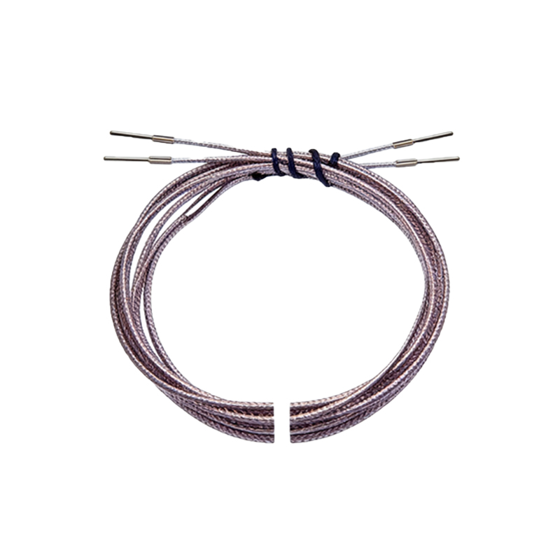
To push the boundaries of sensing range and reliability, advanced technologies are continuously being developed. Background Suppression (BGS) and Foreground Suppression (FGS) sensors use triangulation principles to detect objects only within a precise, adjustable window, effectively ignoring objects beyond or before a set point, which allows for stable detection regardless of target color or reflectivity at the intended range. Laser-based sensors, with their highly collimated beam, offer extremely long ranges and small spot sizes for precise detection of minute objects. Fiber optic sensors, while not extending the raw range of the amplifier unit, allow the sensing head to be placed in tight, harsh, or high-temperature environments, effectively solving range-related placement issues. Time-of-Flight (ToF) and phase-shift measurement principles are also employed in long-range sensors for distance measurement and detection.
Installation and Alignment Best Practices
Proper installation is paramount to achieving the specified sensing range. For through-beam sensors, precise alignment of the emitter and receiver is critical; even a slight misalignment can cause a complete loss of signal. Using alignment tools or listening for the alignment tone on some sensor models is recommended. The sensor should be mounted securely to prevent vibration-induced misalignment. For retro-reflective sensors, ensure the reflector is clean and correctly aligned, and be cautious of "corner cube" reflectors that can tolerate some angular misalignment. With diffuse sensors, the angle of incidence to the target is crucial; perpendicular installation typically yields the maximum range. Always consider the sensor's environmental housing rating (IP67, IP69K) to protect the lens from contaminants that would diminish light transmission and reduce range over time.
Troubleshooting Range-Related Issues
When a photoelectric sensor fails to detect at an expected distance, a systematic troubleshooting approach is required. First, verify the power supply and wiring. Next, clean the sensor's lens and, if applicable, the reflector or receiver lens. Check for obstructions in the light path. Use the sensor's built-in stability indicator (a common feature with LEDs that show signal strength) to assess the received light level. Temporarily test with a standard high-reflectivity target (like white paper) at a close distance to isolate whether the issue is with the sensor or the application conditions (target, environment). If the sensor works with a standard target but not the application target, recalculate the derating factor. Ensure that no other light sources are interfering, and consider using sensors with modulated light and synchronous detection for immunity to ambient light, which can effectively restore the intended sensing range in challenging environments.