Introduction to Metal Proximity Sensors in Ladder Logic
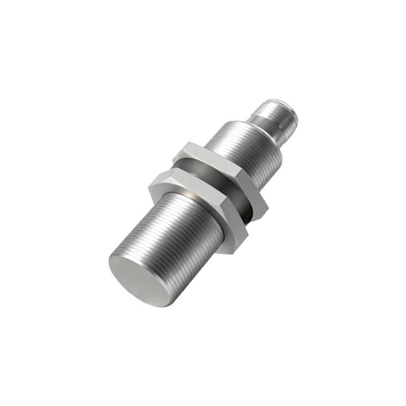
Metal proximity sensors are essential components in industrial automation, widely used for detecting the presence or absence of metallic objects without physical contact. These sensors operate on principles such as inductive sensing, generating an output signal when a metal target enters their detection range. In programmable logic controller (PLC) systems, the functionality of metal proximity sensors is typically represented and programmed using ladder logic diagrams. Ladder logic, a graphical programming language, mimics electrical relay circuits, making it intuitive for engineers to design control systems. This article delves into the integration of metal proximity sensors into ladder logic, explaining their symbols, wiring configurations, and typical programming scenarios to ensure reliable operation in automated environments.
Basic Symbols and Representation in Ladder Diagrams
In ladder logic diagrams, metal proximity sensors are depicted as input contacts, similar to switches or relays. Commonly, a normally open (NO) or normally closed (NC) contact symbol is used, depending on the sensor's default state. For instance, an inductive proximity sensor detecting metal might be shown as an NO contact that closes when a metal object is within range. The symbol includes a label, such as "I1" for an input address, corresponding to the PLC's input module. Wiring diagrams often illustrate the sensor connected to a DC power supply, with the output linked to the PLC input. Understanding these symbols is crucial for accurately interpreting ladder rungs, where sensor contacts control outputs like motors or actuators based on logical conditions.
Wiring Configurations and PLC Integration
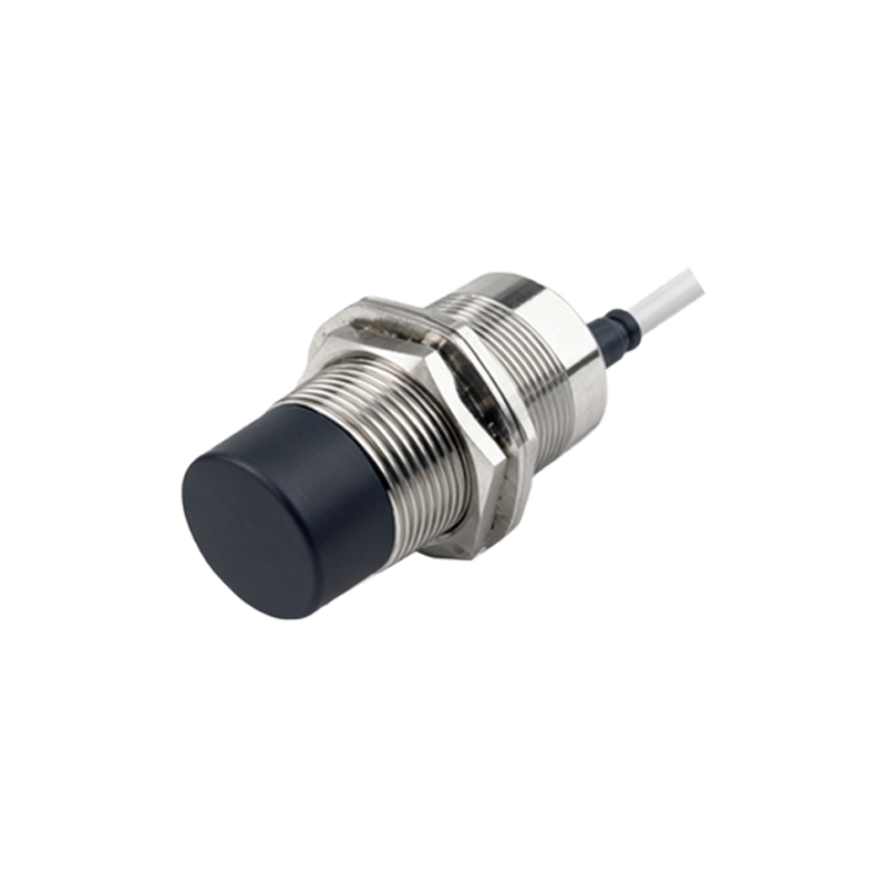
Proper wiring is vital for the effective operation of metal proximity sensors in ladder logic systems. Typically, these sensors are wired in a three-wire configuration: one wire for power (e.g., 24V DC), one for ground, and one for the signal output to the PLC. In ladder diagrams, this corresponds to the input terminal being activated when the sensor detects metal. Engineers must ensure compatibility between the sensor's output type (e.g., PNP or NPN) and the PLC input specifications to avoid malfunctions. For example, a PNP sensor sources current to the PLC, while an NPN sensor sinks it. Ladder logic programming then uses this input status to execute control sequences, such as starting a conveyor belt when a metal part is detected, enhancing automation efficiency.
Programming Examples and Logic Implementation
A practical ladder logic example involves using a metal proximity sensor to control a pneumatic cylinder. Suppose sensor I1 detects a metal component on a production line. In the ladder diagram, contact I1 is placed in series with an output coil O1, which activates the cylinder. When I1 closes upon detection, the rung becomes energized, turning on O1 to extend the cylinder. Additional logic, such as timers or counters, can be integrated for more complex operations—like counting metal parts or delaying actions. Debugging tools in PLC software allow monitoring of sensor status in real-time, ensuring the ladder logic accurately reflects physical processes. This hands-on approach minimizes downtime and optimizes system performance.
Common Challenges and Troubleshooting Tips
Despite their reliability, metal proximity sensors can face issues in ladder logic applications, such as false triggers or no detection. Common causes include incorrect sensor mounting, interference from other metal objects, or wiring errors. In ladder diagrams, these problems may manifest as erratic input states. To troubleshoot, engineers should verify sensor alignment and adjust detection ranges, check for loose connections, and ensure proper grounding. PLC diagnostic functions, like input status indicators, help identify faults quickly. Regular maintenance and calibration of sensors, coupled with clear ladder logic documentation, prevent operational disruptions and uphold safety standards in industrial settings.
Advancements and Future Trends in Sensor Integration
The evolution of metal proximity sensors and ladder logic continues to shape industrial automation. Modern sensors offer enhanced features like longer detection distances, higher switching frequencies, and immunity to environmental factors. In ladder logic programming, advancements include integration with industrial IoT platforms, enabling remote monitoring and data analytics. For instance, sensors can feed real-time data into PLCs, with ladder diagrams processing information for predictive maintenance. As industries adopt smart manufacturing, the synergy between robust sensor technology and intuitive ladder logic will drive efficiency, reducing manual intervention and fostering adaptive control systems.
Conclusion and Best Practices for Engineers
Mastering ladder logic diagrams for metal proximity sensors is key to designing effective automation systems. Engineers should focus on accurate symbol usage, proper wiring, and logical programming to ensure seamless operation. Best practices include testing ladder programs in simulation modes before deployment, documenting all rungs for clarity, and staying updated on sensor innovations. By combining theoretical knowledge with practical experience, professionals can