Introduction to Metal Proximity Sensors
Metal proximity sensors are fundamental components in industrial automation, providing non-contact detection of metallic objects. They operate on the principle of electromagnetic induction, where an oscillator circuit generates a high-frequency electromagnetic field. When a metal object enters this field, eddy currents are induced on the metal's surface, causing a change in the oscillator's amplitude or frequency. This change is detected and converted into a switching signal. Understanding this core principle is crucial before embarking on the construction process. The primary types include inductive proximity sensors, which are most common, and more specialized capacitive or magnetic types for specific applications.
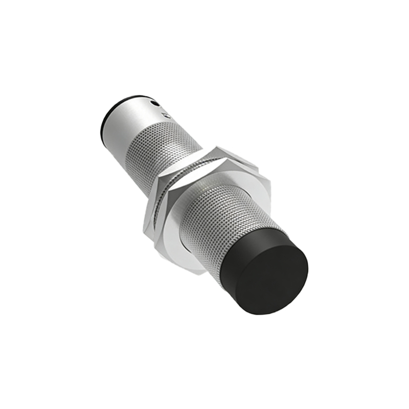
Core Components and Materials Required
To construct a basic inductive metal proximity sensor, you will need several key electronic components. The heart of the sensor is a coil, typically wound from enameled copper wire on a ferrite core to concentrate the magnetic field. An oscillator circuit is built around a transistor or an integrated oscillator chip like the NE555 timer configured in astable mode. You will require capacitors and resistors to set the oscillation frequency, usually in the range of 100 kHz to 1 MHz. A demodulator and trigger circuit, often using a comparator IC like the LM393, are needed to detect the amplitude change. Finally, an output stage, such as an NPN transistor for an NPN sinking output or a relay driver, is necessary. Other materials include a housing (typically metal or PBT plastic for shielding), a sensing face, wires, and a PCB for mounting components.
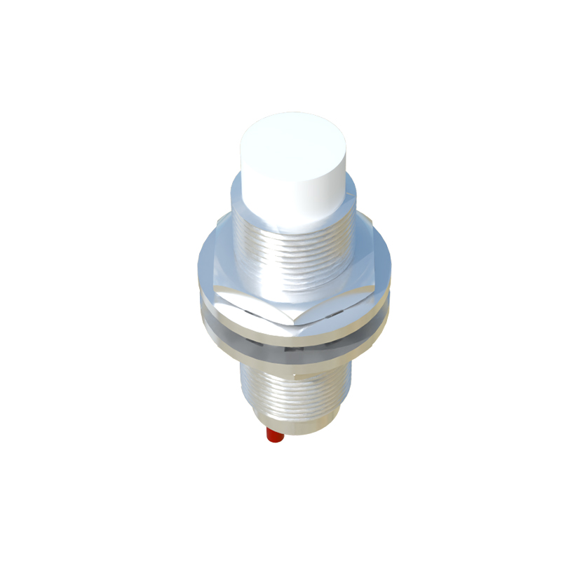
Designing the Oscillator and Sensing Coil
The design of the oscillator and the sensing coil is the most critical step. First, design the coil. The number of turns, wire gauge, and core material determine the inductance and the sensor's sensing range. A typical coil might have 100-200 turns of 0.2mm wire on a ferrite rod. Calculate the inductance (L). Next, design the Colpitts or Hartley oscillator circuit. The oscillation frequency (f) is determined by the formula f = 1 / (2π√(LC)), where C is the capacitance in the tank circuit. Select capacitor values to achieve your desired frequency. A higher frequency generally allows for better detection of non-ferrous metals but may reduce the maximum sensing distance. Use a stable transistor like a BC547 or a dedicated oscillator IC. Ensure the circuit has sufficient gain to sustain oscillations until a metal target dampens them.
Building the Detection and Output Circuit
The raw signal from the oscillator needs to be processed. As a metal object approaches, the oscillation amplitude decreases. This AC signal is fed into a demodulator, which can be a simple diode (e.g., 1N4148) and capacitor peak detector, converting the amplitude change into a DC voltage change. This DC voltage is then fed into a comparator. One input of the comparator receives this voltage, while the other input is connected to a reference voltage set by a potentiometer. This potentiometer allows you to adjust the sensitivity or the switching point. When the signal voltage drops below the reference voltage (indicating metal presence), the comparator output switches state. This digital signal then drives the output stage—an NPN transistor to switch a load connected to the common terminal, providing a clean, usable switch signal.
Assembly and Shielding Considerations
Proper assembly is vital for reliable operation. Wind the coil neatly and secure it with tape or epoxy. Mount all components on a PCB, keeping the oscillator section compact and away from the output stage to prevent interference. The coil should be placed as close as possible to the front sensing face of the housing. Shielding is essential to make the sensor directionally sensitive and immune to nearby metal in its housing or mounting bracket. Encase the coil and oscillator in a metallic shield (often copper or aluminum) that is open only at the sensing face. This shield must be connected to the circuit ground. The housing itself should be made of metal or a metal-filled polymer to provide additional electromagnetic shielding and mechanical robustness.
Calibration and Testing Procedures
After assembly, the sensor must be calibrated and tested. Connect the sensor to its required power supply (typically 12-24V DC). Use an oscilloscope to probe the oscillator node to ensure stable oscillation. Then, bring a standard metal target (usually a square of mild steel of a specified size) towards the sensing face. Adjust the sensitivity potentiometer until the output switches at the desired nominal sensing distance (Sn). Test the sensor's repeatability by moving the target in and out multiple times. Check for hysteresis, which is the difference between the switch-on and switch-off points. Also, test with different metals (steel,