Understanding Sensor Output States
In industrial automation, the terms "Normally Open" (NO) and "Normally Closed" (NC) are fundamental to describing the default electrical state of a sensor's output circuit. This concept is independent of the sensing technology—be it photoelectric, inductive, or capacitive. A "Normally Open" output means the circuit is open (non-conducting) when the sensor is in its idle or non-detected state. Conversely, a "Normally Closed" output is closed (conducting) in that same idle condition. The state switches when a target is detected. For diffuse sensors, the "idle state" is typically when no object is within the preset sensing range.
The Core Principle of Diffuse Sensing
A diffuse reflective photoelectric sensor operates by emitting a beam of light (usually visible red or infrared) from its integrated emitter. When an object enters the detection field, this light strikes the object's surface and scatters in many directions. A portion of this scattered light reflects back to the sensor's receiver. The sensor's internal electronics then evaluate the intensity of this returned light. Crucially, the sensor must be configured to distinguish between the background (no object) and the target object. This is often done via a sensitivity potentiometer or teach-in function to set a detection threshold.
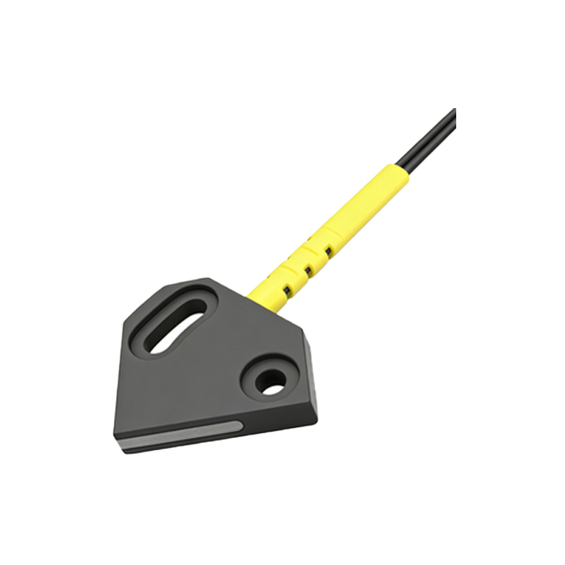
Configurability: The Key to NO/NC Selection
Here is the critical point: whether a diffuse photoelectric sensor is Normally Open or Normally Closed is not a fixed characteristic of the diffuse method itself. It is a function of the sensor's output circuitry and, most importantly, its configurability. The vast majority of modern diffuse reflective sensors feature a programmable or selectable output logic. This means the same physical sensor can be configured by the user, often via a switch, button, or wiring scheme, to operate as either an NO or an NC device. This flexibility is essential for integrating the sensor into different control logic systems (e.g., PLC inputs wired for sinking or sourcing).
Wiring and Integration Considerations
The chosen output state directly impacts system design and safety. For instance, a Normally Closed configuration is often preferred in safety-critical or monitoring applications because a wire break or power loss to the sensor will cause the circuit to open, signaling a fault—a "fail-safe" design. In standard detection tasks, the choice depends on the control logic. If a PLC input card is activated by a "high" signal, and you need that signal when an object is present, you would typically configure the diffuse sensor for a "NO" output. The sensor's datasheet and terminal diagram are paramount; a common three-wire DC sensor will have pins for power supply, ground, and the switched output load wire.
Practical Application Examples
Consider a conveyor belt system. A diffuse sensor is used to detect boxes passing a point. If the control system is designed to start a timer or increment a counter upon detection, the sensor should be configured as Normally Open. In its idle state (no box), the output is off. When a box reflects light back, the output switches on, sending the signal. Conversely, imagine a sensor monitoring the presence of material in a hopper to prevent overfilling. A Normally Closed configuration might be used here. The output is on while material is absent, and it switches off when material reaches the level, triggering the "stop fill" command. This can provide a continuous confirmation that the monitoring loop is intact.
How to Determine and Set the Output State
Always consult the manufacturer's documentation first. Look for terms like "output logic," "light/dark operation," or "NO/NC selectable." Many sensors have a small selector switch. "Light-ON" (or "L-ON") mode typically corresponds to the output activating when light is received, which for a diffuse sensor means an object is present—this is often equivalent to a Normally Open behavior. "Dark-ON" ("D-ON") mode activates the output when the received light falls below the threshold (object absent), often aligning with Normally Closed logic. Testing with a multimeter or a PLC input indicator is the best practice after configuration to verify the real-world behavior matches the system requirements.