Understanding Proximity Sensor Fundamentals
Proximity sensors are the silent sentinels of modern industrial automation. These non-contact devices detect the presence or absence of an object within their sensing field, triggering critical actions in machinery and processes. Predominantly, they fall into three main categories: inductive (for metallic objects), capacitive (for both metallic and non-metallic materials), and photoelectric (using light beams). Each type operates on distinct physical principles, which directly informs their specific maintenance needs and failure modes. A deep understanding of whether your operation relies on inductive sensors for metal detection on a conveyor or capacitive sensors for liquid level control is the foundational step toward effective, proactive maintenance. Knowing the sensor's rated operating distance, environmental ratings (IP codes), and output type (PNP/NPN, analog) is equally crucial for troubleshooting and parts management.
Establishing a Proactive Maintenance Schedule
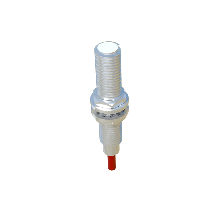
Reactive maintenance, or fixing sensors only after a failure, leads to costly unplanned downtime. A proactive, scheduled maintenance program is essential for maximizing sensor lifespan and system reliability. This schedule should be risk-based, prioritizing sensors in critical or harsh applications. For most industrial environments, a quarterly visual and functional inspection is a good starting point. This involves checking for physical damage, accumulation of debris, and ensuring secure mounting and electrical connections. Annually, a more comprehensive calibration and performance verification against known standards should be performed. Maintenance logs are vital; they track sensor history, common failure points, and help predict end-of-life, enabling orderly replacement before catastrophic failure disrupts production.
Routine Inspection and Cleaning Procedures
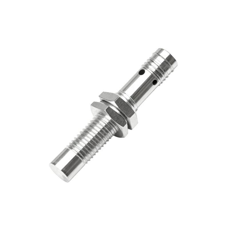
Daily or weekly visual checks can prevent many common sensor issues. For inductive and capacitive sensors, the active sensing face must be kept clean and free from metal shavings, dust, oil, or coolant buildup. A soft, lint-free cloth is typically sufficient for cleaning. Avoid using abrasive materials or harsh chemicals that could damage the sensor housing or sensing face. For photoelectric sensors, meticulously clean the lens and reflector with appropriate optical cleaning solutions to maintain signal strength. Simultaneously, inspect the sensor's mounting hardware for loosening due to vibration and verify that cabling is undamaged and not subjected to excessive stress or heat. Ensure the sensing distance to the target has not changed due to mechanical drift.
Diagnosing Common Failure Modes
Even with excellent maintenance, sensors can fail. Rapid diagnosis is key. Common symptoms include intermittent operation, failure to detect, constant activation, or output signal drift. For inductive sensors, a common issue is reduced sensing range, often caused by a buildup of ferrous material on the face or degradation of the oscillator circuit. Capacitive sensors can be falsely triggered by environmental changes like humidity or contamination. Photoelectric sensors suffer from misalignment, dirty optics, or ambient light interference. Use a multimeter to check supply voltage and output signals. Many modern sensors have built-in LED indicators that provide valuable diagnostic information about power status and output switching, which should be the first point of reference.Calibration and Performance Verification
Over time, a sensor's performance can drift from its original specifications. Regular calibration ensures accuracy and reliability. This process involves testing the sensor's response with certified target materials at specified distances. For critical applications, this might require sending sensors to a certified lab. However, in-plant verification using go/no-go gauges or shims of known thickness is a practical and highly effective method. Document the "as-found" and "as-left" conditions. For analog sensors, verifying the linearity of the output signal across its range is also important. Performance verification not only catches drift but also helps identify sensors that are degrading gradually, allowing for planned replacement.
Environmental Considerations and Protection
The operating environment is the greatest factor influencing sensor longevity. Extreme temperatures, humidity, corrosive chemicals, washdowns, and intense vibration all take their toll. Always select sensors with an Ingress Protection (IP) rating suitable for the environment—for example, IP67 for dust-tight and temporary immersion. Use protective accessories like mounting brackets to position sensors away from direct spray or physical impact. Consider stainless-steel housings for corrosive or washdown areas. For high-vibration applications, ensure wiring is properly strain-relieved and connections are secure. Environmental protection isn't a one-time task; it requires ongoing vigilance to ensure seals remain intact and conditions haven't changed.
Spare Parts Management and Lifecycle Planning
A strategic spare parts inventory prevents extended downtime. Analyze maintenance logs to identify sensors with high failure